Designing Printed Circuit Boards

Designing Printed Circuit Boards (PCBs) is not as hard as it seems. A couple of years ago I got into embedded electronics as a hobby and since then I have designed a couple of boards for simple projects. I used CadSoft’s EAGLE PCB design software. The learning curve was (is, because I think I am still learning) steep but there are good tutorials to be found on-line, including a tutorial from CadSoft itself.

Obviously, after designing a board you will want to manufacture it, either by yourself or by paying someone to do it cialis 10mg bestellen. In either case, catching errors in the design before the board is manufactured will prevent frustrations after you have the board in your hands and notice during testing that it does not work because of some problem like incorrect part footprints, incorrect board size, etc.

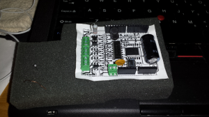
What I have done a couple of times to try to catch problems before it is too late has been to make a 1:1 copy of the board, glue it to some material that allows to stick real parts to it, and then lay out the parts on top, as shown in the following picture:

Nothing earth-shattering but it definitely has been useful and saved me a couple of times.

Upload non-Arduino firmware to Arduino-compatible board

The Atmel AVR family of microcontrollers is our favorite solution for embedded electronic projects. As you know, this family is what the popular Arduino platform uses cialis preis apotheke. However, for our projects we have never used the Arduino integrated development environment (IDE), or Arduino libraries. Instead, we have stuck with AVR libc mainly so we can have more control over our firmware and to try to have firmware with a smaller footprint in terms of both execution and image size.

Because we have not been using the Arduino IDE, we have always uploaded firmware to the AVR microcontroller using an in-system programmer (ISP) (the ISP programmer we use is the inexpensive USBtiny). This has been a requirement because our microcontrollers do not normally have a boot loader that allows them to be flashed via the serial port, unlike the Arduino, which does not expose the SPI through a connector that allows someone to hookup an ISP programmer, and therefore has to be programmed

Recently, however, we bought a Moteino, a very nice Arduino-compatible board, that has a boot loader that is compatible with the Arduino IDE. This required us to come up with a way to upload firmware to this board. We originally thought about soldering an adapter to use the AVR’s Serial Peripheral Interface (SPI), which uses the three signals Serial ClocK (SCK), Master In-Slave Out (MISO) and Master Out-Slave In (MOSI), and then use our USBtiny ISP programmer.

However, it turns out that is a lot easier than that — the AVRDUDE software can actually program Arduino-compatible boards directly, without using the SPI interface. We probably should have guessed this because, as we understand it, the Arduino IDE actually uses AVRDUDE to upload firmware to the target.

A sample AVRDUDE invocation looks like this:

shell$ avrdude -p atmega328p -c arduino -P /dev/ttyUSB2   -y -U flash:w:primus.hex

This is what the command-line arguments do:

  • -p atmega328p: specifies the type of target microcontroller.
  • -c arduino: specifies the programmer type. We understand that stk500v1 should work, and we have seen online references that seem to indicate that is what the Arduino IDE uses, but stk500v1 did not work for us. Instead, our AVRDUDE executable (from Ubuntu 13.10) does have an “arduino” programmer that worked very well.
  • -P /dev/ttyUSB2: this is the device to use to talk to the Arduino-compatible target.
  • -U flash:w:primus.hex: this is the name of the firmware file to upload to the Arduino-compatible target.

When we use our ISP programmer, one argument that we like to use is -y, which increments a 16-bit counter stored in the last two bytes of the AVR EEPROM (this counter has to be initialized with a one-time AVRDUDE invocation that uses the arguments -W <initial counter value>). We found out that the boot loader used by Arduino and Arduino-compatible boards (apparently Optiboot) does not handle AVR EEPROM access, so the use of -y when invoking AVRDUDE to upload flash to the Arduino-compatible board is not possible (and neither is initializing the counter with -Y, nor uploading EEPROM data using -U eeprom:w:data.hex).

But this is a small price to pay for the convenience of uploading our AVR libc firmware without having to use the Arduino IDE.

Add More Disk Space To Existing Ubuntu 12.04 Server Installation

Recently we found ourselves regretting a decision we made when we installed Ubuntu Server 12.04LTS on a VMware ESXi virtual machine (VM) — when we created the VM, we allocated a very small hard disk (8 GBytes) thinking that for the specific purpose of that machine we were not going to need a bigger hard drive. It turns out that we were very wrong, which became apparent when we tried to download a 4+ GByte file and the download failed because of lack of free space.

Because we did not want to create a new VM and copy the existing installation over we decided to just increase the size of the existing disk and the partitions/physical volumes/logical volumes inside it. Turns out this was not as easy as we thought so we decided to document things here. We basically followed the instructions in this blog post (credit where credit is due):

http://www.joomlaworks.net/blog/item/168-resizing-the-disk-space-on-ubuntu-server-vms

Increasing the size of the actual hard disk is very easy because we are working with a virtual machine — all it takes is to is to edit the virtual machine settings, look for the virtual disk, and increase the size (we have done this for both VMware and VirtualBox virtual machines; the process is similar). The difficult part comes after increasing the size of the virtual disk — the existing stuff inside the hard disk needs to be resized as well.

Several links we found online talked about booting the machine with an Ubuntu LiveCD and then using GParted (a GUI-based partition utility) to resize the existing partition to make use of the new, extra unallocated space. We did not have any luck with that.

Instead, what we found worked for us was to just make use of the Linux Logical Volume Manager (LVM), which is what was set up by the Ubuntu installer when we first installed Ubuntu on this machine. Basically, the process looks like this:

  1. Create a new logical partition using the new unallocated space.
  2. Create a new physical volume that uses the new partition.
  3. Extend the existing Volume Group that was created during Ubuntu installation to make use of the new physical volume.
  4. Extend the Logical Volume to make use of the new available space.
  5. Resize the filesystem to make use of the new available space.

We will go in detail on each of these steps.

Create New Logical Partition

We used cfdisk. Basically, select the unallocated (free) space, then select the “New” option, then “Logical”, and allocate all the available space (shown by default). Select “Type” and enter “8e” (for Linux LVM). Finally select “Write”, confirm by typing “yes” followed by <Enter>, then “Quit”, and reboot the machine.

This is how the partition table looked before using cfdisk:

root@holyland:~# fdisk -l /dev/sda

Disk /dev/sda: 268.4 GB, 268435456000 bytes
255 heads, 63 sectors/track, 32635 cylinders, total 524288000 sectors
Units = sectors of 1 * 512 = 512 bytes
Sector size (logical/physical): 512 bytes / 512 bytes
I/O size (minimum/optimal): 512 bytes / 512 bytes
Disk identifier: 0x0009f8ab

   Device Boot      Start         End      Blocks   Id  System
/dev/sda1   *        2048      499711      248832   83  Linux
/dev/sda2          501758    16775167     8136705    5  Extended
/dev/sda5          501760    16775167     8136704   8e  Linux LVM

And this is how the partition table looks like after using cfdisk to create the new partition on the free space and rebooting the machine. Note the new partition /dev/sda6:

root@holyland:~# fdisk -l /dev/sda

Disk /dev/sda: 268.4 GB, 268435456000 bytes
255 heads, 63 sectors/track, 32635 cylinders, total 524288000 sectors
Units = sectors of 1 * 512 = 512 bytes
Sector size (logical/physical): 512 bytes / 512 bytes
I/O size (minimum/optimal): 512 bytes / 512 bytes
Disk identifier: 0x0009f8ab

   Device Boot      Start         End      Blocks   Id  System
/dev/sda1   *        2048      499711      248832   83  Linux
/dev/sda2          501758   524287999   261893121    5  Extended
/dev/sda5          501760    16775167     8136704   8e  Linux LVM
/dev/sda6        16775231   524287999   253756384+  8e  Linux LVM

Create New Physical Volume

To create a new physical volume in the new partition we used pvcreate:

root@holyland:~# pvcreate /dev/sda6
  Physical volume "/dev/sda6" successfully created

Extend Existing Volume Group

First, we need the name of the volume group. This can be obtained by running the vgdisplay command:

root@holyland:~# vgdisplay
  --- Volume group ---
  VG Name               holyland
  System ID            
  Format                lvm2
  Metadata Areas        1
  Metadata Sequence No  3
  VG Access             read/write
  VG Status             resizable
  MAX LV                0
  Cur LV                2
  Open LV               2
  Max PV                0
  Cur PV                1
  Act PV                1
  VG Size               7.76 GiB
  PE Size               4.00 MiB
  Total PE              1986
  Alloc PE / Size       1978 / 7.73 GiB
  Free  PE / Size       8 / 32.00 MiB
  VG UUID               H5FfHu-lsxo-G9Od-k8S5-lnCQ-PuCq-059Xco

The output above (under “VG Name”) shows that the name of the volume group is “holyland” (the name of our server).

Next we use the vgextend command to extend the existing volume group to the new physical volume:

root@holyland:~# vgextend holyland /dev/sda6
  Volume group "holyland" successfully extended

Extend The Logical Volume

First, we need to obtain the name of the logical volume that we want to extend (this is because a volume group can contain several logical volumes). To obtain the name of the logical volume with use the lvdisplay command:

root@holyland:~# lvdisplay
  --- Logical volume ---
  LV Name                /dev/holyland/root
  VG Name                holyland
  LV UUID                vNPQV1-s5OU-GYVP-FCMp-p3UY-7fhe-FXNsK8
  LV Write Access        read/write
  LV Status              available
  # open                 1
  LV Size                7.23 GiB
  Current LE             1851
  Segments               1
  Allocation             inherit
  Read ahead sectors     auto
  - currently set to     256
  Block device           252:0

  --- Logical volume ---
  LV Name                /dev/holyland/swap_1
  VG Name                holyland
  LV UUID                YxBsBD-we0S-ELCV-yCsz-RAdL-Qzcj-y4cpH9
  LV Write Access        read/write
  LV Status              available
  # open                 2
  LV Size                508.00 MiB
  Current LE             127
  Segments               1
  Allocation             inherit
  Read ahead sectors     auto
  - currently set to     256
  Block device           252:1

We are interested in extending the logical volume used for the root filesystem, which corresponds to the logical volume called “/dev/holyland/root” in the output above (under “LV Name”).

To extend the logical volume we are interested in, we use the lvextend command as follows:

root@holyland:~# lvextend -l 100%FREE /dev/holyland/root
  Extending logical volume root to 242.03 GiB
  Logical volume root successfully resized

Note the use of of the “-l 100%FREE” argument, which indicates that we want to extend the logical volume to use 100% of the free space.

Extend Filesystem

Finally, to extend the file system we use the resize2fs command:

root@holyland:~# resize2fs /dev/holyland/root
resize2fs 1.42 (29-Nov-2011)
Filesystem at /dev/holyland/root is mounted on /; on-line resizing required
old_desc_blocks = 1, new_desc_blocks = 16
The filesystem on /dev/holyland/root is now 63447040 blocks long.

To verify, we use the df command:

root@holyland:~# df -hT
Filesystem                Type      Size  Used Avail Use% Mounted on
/dev/mapper/holyland-root ext4      239G  3.8G  225G   2% /
udev                      devtmpfs  237M  4.0K  237M   1% /dev
tmpfs                     tmpfs      99M  260K   98M   1% /run
none                      tmpfs     5.0M     0  5.0M   0% /run/lock
none                      tmpfs     246M     0  246M   0% /run/shm
/dev/sda1                 ext2      228M   75M  141M  35% /boot

Now the root filesystem has a healthy size!

Mixed Content Blocking in Firefox 23

A website that I use at work all of the sudden started to render in a very broken way. Since we had had similar issues in the past I originally thought that it was a problem on the web application itself. However, after asking a co-worker I learned that the breakage is caused by a new feature that is enabled by default in Firefox 23: mixed content blocking. The feature is explained well at the following URL, but it basically boils down to “Firefox will block HTTP content referenced from a page served over HTTPS”.

https://blog.mozilla.org/tanvi/2013/04/10/mixed-content-blocking-enabled-in-firefox-23/

The feature is a nice security feature. However, I think it has been terribly implemented in my opinion — first, you cannot create persistent exceptions (whitelist); second, you cannot create exceptions for entire domain (you have to create them on a page by page basis) so next time you open a page on the same site that also has mixed content then the mixed content will be blocked too. For the second issue, reading the comments in Mozilla bug 873349 is enlightening.

So, I can appreciate all the work the Mozilla developers have put into this feature but I have no option other than to disable it because it really puts a dent on my productivity. Let’s see if this feature is enhanced in a future Firefox release.

ZoneMinder Memory-Mapped Files

After tweaking the capture image size of some of the IP cameras connected to our ZoneMinder installation we started to get the following error in the ZoneMinder log right after launching a viewer to watch the camera’s video stream:

Got unexpected memory map file size 36865192, expected 9217192

Googling for this error took us to this blog post:

http://jared-oberhaus-tech-notes.blogspot.com/2011/12/im-trying-to-capture-video-from-device.html

Which in turn took us to the ZoneMinder FAQ.

The recommendation is to increase the setting /proc/sys/kernel/shmmaxsize so ZoneMinder has enough memory to memory-map the files it needs during streaming.

However, upon checking our /proc/sys/kernel/shmmaxsize setting we found that it had pretty high setting (the recommended [in the ZoneMinder FAQ] 536870912, for 128 MB of maximum shared memory allocatable at a time), because we had run into the issue before and tried to fix it by following the recommendation in the ZoneMinder FAQ. In addition, the error message indicates that it expects a file with a size that is smaller than it currently has, so increasing the /proc/sys/kernel/shmmaxsize setting would not have fixed the problem.

It turns out that ZoneMinder had created the memory-mapped file for a specific capture image size:

$ ls -l /dev/shm/
 total 90016
 -rw------- 1 www-data www-data 36865192 Apr 9 08:24 zm.mmap.6
 [...]

And when we changed the capture image size to a smaller resolution, the required size of the memory-map filed decreased. However, because ZoneMinder had not been restarted, the memory-mapped file had not been recreated, and it still had the size that ZoneMinder allocated for the original, higher resolution video capture.

Re-starting ZoneMinder caused the memory-mapped file to be recreated, now with the correct size for the new (smaller) capture image size:

$ ls -l /dev/shm/
 total 63016
 -rw------- 1 www-data www-data 9217192 Apr 9 08:47 zm cialis online ohne rezept.mmap.6
 [...]

After this, ZoneMinder did not generate the error anymore.

Update 20130415:

We increased the capture image size of one of the ZoneMinder monitors and received again the “Got unexpected memory map file size …” message, this time indicating that the size of the file is smaller than expected. This makes sense and shows that the issue has nothing to do with the configured value in /proc/sys/kernel/shmmaxsize but with a memory-mapped filed created by ZoneMinder that is not recreated when the size of the image capture is changed. This should be considered a bug in ZoneMinder, in our opinion. We are running ZoneMinder 1.25.0.

Orbit 62035 Redux

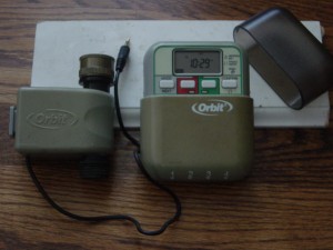
The Orbit 62035 water valve was part of a yard watering system sold by Orbit around 2005 (it has been superseded by a newer generation of valves, and their corresponding timer/controller, although it is probably still possible to find the old valves on Amazon or eBay). This yard watering system, and its valves, were sold in the United States at big retailers like Lowes, The Home Depot, and BJs. We bought two of these systems, which includes a couple of 62035 water valves and their controller (timer) to water our front and back yards, and they have been working wonderfully for about six summers. The following picture shows a 62035 water valve and its controller (click image to enlarge). Note from the picture the 3.5 mm connector and that the controller can control up to four valves.

The controller is pretty good and user-friendly, and the three AA batteries it uses to run last a long time, but for a while we have wanted to be able to control the valves from a computer, or to have more intelligence on the controller itself, like taking into consideration whether it has rained, or that the forecast calls for rain soon, because it is not fun to go outside in the middle of the night and in the middle of a thunderstorm to override the system so it does not waste water the next morning. This sent us into a quest to figure out how to control these valves to then try to build a controller that suits our needs. (Note: Sure, without a doubt there is something that can be bought that will suit our needs, but we also have fun doing this ourselves, which is why we do it.)

What we found was that some people had already, for the most part, figured out the specifications of the valve, and even built drivers to operate them. Here are the relevant links that we found:

There was a lot of information, but some of it seemed contradictory or insufficient. For instance, here is what we were able to gather regarding the valves, their specifications, and how to make them work:

  • There are two latching solenoids, one for opening the valve and another for closing it.
  • The standard 3-pin 3.5mm stereo audio plug used by the valve uses a common contact to supply the voltage required for operation, and separate contacts for the open and close solenoids.
  • The resistance of each solenoid was different. One (the open solenoid) was around 4 ohms, but the other (the close solenoid) had a fairly low resistance of around 1 ohm.
  • The voltage required to operate the valves was not clear — some people thought it was 24 volts, some others claimed it was 17 volts, and then Orbit technical support claimed it was 13 volts.
  • The original Orbit controller works by charging a 2,200 uF capacitor and then discharging it through the solenoids. To charge the capacitor, and because the controller only uses three AA batteries, a voltage booster circuit is used. Our guess would be that the exact value of the capacitor was found after someone opened the original Orbit controller and took a peek at the components inside.
  • In one of the links above someone claims that to close the valve the controller first sends an open pulse followed by the big close pulse.
  • The length of the pulse needed to open or close the solenoids, per someone that apparently watched the operation on an oscilloscope, was around 22 milliseconds, although Orbit technical support provided a different figure.
  • Since the resistance of the close solenoid is so low, there is a 3.9 ohm current-limiting resistor. This was discovered after some people (Ray) opened an original Orbit controller and saw the 3.9 ohm resistors.
  • Orbit support, supposedly, provided the following specifications for these valves: 13V, 22ms pulse and 1 to 1.5 amp current max.

Armed with this information we tried to recreate the circuits that others had designed. We managed to make things to work on a breadboard, with some minor modifications of our own, but when we moved the design to SMT devices on a real PCB, things did not work.

So, to be able to figure out why our SMT design was not working we decided to hook up the original Orbit controller to an oscilloscope and collect some data. This is what we found after we connected an oscilloscope to the original Orbit controller and a 62035 water valve…

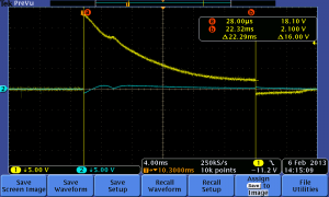
The following oscilloscope screenshot shows the original Orbit controller opening an Orbit 62035 valve (click image to enlarge):

The yellow line is the voltage applied to the solenoid that opens the valve and the blue line is the voltage at the solenoid that closes the valve. The graph shows a capacitor discharging through the solenoid (a resistance with a low value). The initial voltage is 18.1 volts. Not 24 volts as originally thought, and not the 13 volts that Orbit technical support claimed, though both voltages are close. The 0 volts across the close solenoid makes sense. Note also the length of the pulse — 22 milliseconds. The resistance we measured across the solenoid that opens the valve is 4.2 ohms, which means that at the beginning of the discharge there is a peak current of 18.1 volts/4.2 ohms = 4.2 Amps.

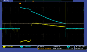
Finally, the following oscilloscope screenshot shows the original Orbit controller closing an Orbit 62035 valve (click image to enlarge):

A few things to note here: First, notice the different vertical scale — 0.5 volts/division. Next, note that we forgot to turn on the cursor so we can easily see the the exact voltage at the trigger point, but it is easy to see that the blue line (voltage across the close solenoid, as in the first screenshot) has a value at trigger point of 4 divisions x 0.5 volts/division = 2 volts. Since the resistance of the close solenoid is different (0.9 ohms), then at the beginning of the discharge the peak current is approximately 2 volts/0.9 ohms = 2.2 Amps. The length of the pulse is also about 20 milliseconds. This opens two possibilities with regards to the value to which the 2,200 uF capacitor is charged: 1. it is charged to a lower voltage than the voltage it is charged to in the case of opening the valve, or 2. it is charged to the same value (~ 18 volts) but there is a resistor in series with the solenoid to limit the current. (2) is what is actually happening based on Ray’s findings, i.e. there is a 3.9 ohm capacitor inside the original Orbit controller, but it would be interesting to experiment with (1) to see if in our design we could somehow (through software, assuming we can control the voltage produced by the voltage booster circuit) eliminate the current limiting resistor.

Another interesting thing to note is the negative voltage across the open solenoid — this seems to be the pulse that one of the people participating in this discussion mentioned, though we are not sure it is the same thing because in the discussion the gentleman says ‘When the Timer/Controller turns a valve OFF, it first operates the “Valve ON” coil, then recharges the capacitor and operates the “Valve OFF” coil’, and we did not see this exact behavior, as the above screenshot shows.

In a future post we will look at how we are planning to control the Orbit 62035 valve based on the information we have learned through the research done by others as well as our own observations.

Capacitor Discharge

I am working on a project that requires activating a latching solenoid cialis auf rezept. I am trying to accomplish this by discharging a capacitor through the solenoid. I have the “supposed” specifications of the voltage, current and pulse time needed for the solenoid to be activated so it helps to understand the behavior of the capacitor discharge. This is Electricity 101, which I studied many moons ago, and which I remember nothing about, unfortunately.

Fortunately, there are plenty of resources out there that explain what happens when a capacitor is discharged through a resistance and calculators that allow you to plug in some basic parameters and then present you with final voltage of the capacitor. Here are some references:

RC circuits: http://en.wikipedia.org/wiki/RC_circuit

Some online calculators that I found:

http://www.learningaboutelectronics.com/Articles/Capacitor-discharge-calculator.php

http://hyperphysics.phy-astr.gsu.edu/hbase/electric/capdis.html

http://planetcalc.com/1979/

BJT Base Resistor Value

It is very common to use <a href="http://en.wikipedia cialis 20mg filmtabletten apotheke.org/wiki/Bipolar_junction_transistor”>bipolar junction transistors (BJT) to drive higher current loads. For example, BJTs is commonly used to drive LEDs, electric motors, relays, etc.

When using a BJT to drive a higher current load a resistor needs to be put between the signal driving the transistor and the transistor’s base. The purpose of this transistor is to limit current going into the base. The resistor’s value is important and should be calculated depending on the circuit’s operating parameters and the load the transistor is driving.

I have never been too serious about calculating base resistor values… until today when a circuit I was working on did not work. Upon closer inspection I realized that I had used in my breadboard prototype a different resistor value than the value of the resistor that I used in the PCB version of the same circuit — in the breadboard test I had used 100 ohms and in the PCB I soldered a 1 kohm resistor. As a consequence, my circuit was not able to drive well the solenoid that I was driving with this transistor. (The mistake, by the way, was caused by incorrect resistor value in the Eagle schematic, which got into my PCB circuit because I was following the schematic and not the breadboard prototype while assembling the PCB. Ggrrr. Note to self: make sure your schematic reflects your working prototype.)

Fortunately, calculating the correct base resistor value is easy, and there are online calculators out there that help with this task. You need to know:

  • Ic — the collector current (the current going through your load)
  • The hFE (gain) of the transistor. This varies depending on the collector current, and its value can be determined from the data sheet
  • The voltage drop across the base to emitter junction. This is called Vbe(sat) in the transistor’s data sheet
  • The voltage used to drive the transistor (at the base). This is typically the voltage supplied by a microcontroller output pin, and is usually very close to the supply voltage to the microcontroller (typical values: 5 V, 3.3V)

Here’s a link to a great online calculator:

http://kaizerpowerelectronics.dk/calculators/transistor-base-resistor-calculator/

The author of this calculator described the formula in the comments of that post as follows:

(Supply voltage – voltage drop) / (Collector current / Hfe)

Finding the parameters needed for this formula (which are very well explained at the top of the above calculator page) is a great way to learn how to read a transistor’s data sheet.

First post!

Since this is the first post in this blog I think it is appropriate to do a little introduction and write about what I am hoping this blog will be about, and what I will try to accomplish with it, so let’s start there…

First of all, I am hoping that having a personal blog will allow me to learn about blogging, which is something that I have never done before. A lot of people are <a href="http://monicalinares internetapotheke cialis.wordpress.com”>blogging these days, and it seems like blogging is a good way to let others know about ideas and projects you are working on.

Since I didn’t want to just go to one of the common blogging sites to create my blog, I decided to install WordPress on my own server and go through the configuration process from scratch. Fortunately, installing WordPress on Ubuntu is just a matter of running apt-get install wordpress. Configuration so far has been pretty easy so there really isn’t much to learn in this area, but I digress…

In terms of content, I honestly think that the only rule is that there are no rules in terms of content that is appropriate for this blog. I have ideas regarding what I would like to write about, but I reserve the right to write about something that is not part of my initial set of ideas.

Specifically, I would like to write about:

  • Adventures in home automation
  • Electronic projects I am working on, or would like to work on
  • Anything related to technology
  • Computers
  • Computer networks
  • Anything my curiosity takes me to…