Site-to-site VPN Between AWS And OpenWRT With strongSwan

We recently had to configure a site-to-site IPsec-based VPN connection between AWS and a small router running OpenWrt 19.07. This post goes over the details so we remember what we did next time we have to do this…

OpenWrt

On the OpenWrt side, what is used is strongSwan. We tried to use as much OpenWrt “configuration flavor” as possible thinking that if we follow the way things are configured in OpenWrt future upgrades might be easier as configuration would not get lost.

To start, on OpenWrt we installed the following packages using opkg:

  1. kmod-ip-vti
  2. strongswan-minimal
  3. vti
  4. vti4

We then added the following to /etc/ipsec.conf (AWS makes it easy by providing this as a template, which you can download from AWS VPC service -> VPN -> Site-to-Site VPN Connections):

conn AWS-Tunnel1
auto=start
left=%defaultroute
leftid=65.x.x.x
right=18.x.x.x
type=tunnel
leftauth=psk
rightauth=psk
keyexchange=ikev2
ike=aes128-sha1-modp1024
ikelifetime=8h
esp=aes128-sha1-modp1024
lifetime=1h
keyingtries=%forever
leftsubnet=0.0.0.0/0
rightsubnet=0.0.0.0/0
dpddelay=10s
dpdtimeout=30s
dpdaction=restart
## Please note the following line assumes you only have two tunnels
## in your Strongswan configuration file. This "mark" value must be
## unique and may need to be changed based on other entries in your
## configuration file.
mark=100

conn AWS-Tunnel2
auto=start
left=%defaultroute
leftid=65.x.x.x
right=19.x.x.x
type=tunnel
leftauth=psk
rightauth=psk
keyexchange=ikev2
ike=aes128-sha1-modp1024
ikelifetime=8h
esp=aes128-sha1-modp1024
lifetime=1h
keyingtries=%forever
leftsubnet=0.0.0.0/0
rightsubnet=0.0.0.0/0
dpddelay=10s
dpdtimeout=30s
dpdaction=restart
## Please note the following line assumes you only have two tunnels in your Strongswan configuration file. This "mark" value must be unique and may need to be changed based on other entries in your configuration file.
mark=200

The following was added to /etc/ipsec.secrets:

65.x.x.x 18.x.x.x : PSK "PSK1 goes here"
65.x.x.x 19.x.x.x : PSK "PSK2 goes here"

The following was added to /etc/config/network (this creates the VTI interfaces on Linux):

config interface 'vti1'
option proto 'vti'
option mtu '1500'
option tunlink 'wan'
option peeraddr '18.x.x.x'
option zone 'vpn'
option ikey '100'
option okey '100'

config interface 'vti1_static'
option proto 'static'
option ifname '@vti1'
list ipaddr '169.254.132.86/30'

config interface 'vti2'
option proto 'vti'
option mtu '1500'
option tunlink 'wan'
option peeraddr '19.x.x.x'
option zone 'vpn'
option ikey '200'
option okey '200'

config interface 'vti2_static'
option proto 'static'
option ifname '@vti2'
list ipaddr '169.254.133.142/30'

config route
option target '10.0.0.0/8'
option interface 'vti1_static'

config route
option target '10.0.0.0/8'
option metric '10'
option interface 'vti2_static'

(The IP addresses under the vtiX_static interfaces are for the point-to-point link. AWS provides those.)


AWS

Step 1: Log into your AWS account and go to Services -> VPC

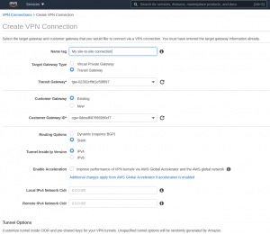
Step 2: Under “Virtual Private Network (VPN)”, go to “Customer Gateways” and create a new customer gateway. We chose “static” routing for this example.

One can attach a site-to-site connection to a Virtual Private Gateway, or to a Transit Gateway. Because our AWS infrastructure had a Transit Gateway we chose to attach the new site-to-site VPN connection to it, so we did not have to create a Virtual Private Gateway.

Step 3: Go to “Virtual Private Network (VPN)” -> “Site-to-Site VPN Connections” and create your site-to-site VPN connection.

Note local and remote IPv4 network CIDRs — they are empty, which means 0.0.0.0/0. That is what we want and it means that we will send through the VPN tunnel whatever needs to be sent based on routing tables. This type of VPN is called “route-based” VPN, and contrasts with “policy-based” VPN.

Note also that from “Virtual Private Network (VPN)” -> “Site-to-Site VPN Connections”  is where you can download IPsec configuration tempates for VPN gateways from different vendors. In our case, because our VPN gateway is a router running strongSwan-based IPsec running on OpenWrt, we chose “Strongswan”, as shown in the following screenshot:

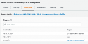
Step 4: Every subnet in your AWS VPC that needs to reach your remote site must have in its route table a route to your remote subnet that points to your Transit Gateway. To (in our case, statically) configure this, go to “Virtual Private Cloud” -> “Subnets”, select the subnet that needs to reach your remote network, edit, and add a static route. For example:

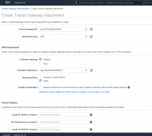
Step 5: Create a Transit Gateway Attachment in “Transit Gateways” -> “Transit Gateway Attachments”. This links your Transit Gateway and your Customer Gateway.

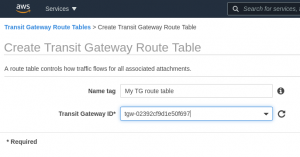
Step 6: Finally, create a route table for your Transit Gateway in “Transit Gateways” -> “Transit Gateway Route Tables”. Only the Transit Gateway needs to be specified:

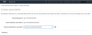
Edit the Transit Gateway route table that you just created and create an association to the the attachment you created in step #5:

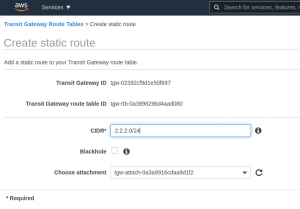
Create a new static route in the Transit Gateway route table that you just created and that uses your VPN attachment:

That should be it — after all this your VPN tunnels should come up.

Monitoring

In AWS, you will see the status of your tunnels in VPC -> Virtual Private Network (VPN) -> Site-to-Site VPN Connections -> select your VPN site-to-site connection -> “Tunnel Details” tab. For example:

In OpenWrt you can use the command “ipsec statusall” to get details about the tunnels. For example:

root@Shangri-La:~# ipsec statusall
Status of IKE charon daemon (strongSwan 5.8.2, Linux 4.14.221, mips):
uptime: 7 days, since Mar 22 14:57:27 2021
worker threads: 11 of 16 idle, 5/0/0/0 working, job queue: 0/0/0/0, scheduled: 6
loaded plugins: charon aes sha1 random nonce x509 pubkey gmp xcbc hmac kernel-netlink socket-default stroke updown
Listening IP addresses:
10.10.10.1
65.x.x.x.x
[...]
Connections:
AWS-Tunnel1: %any...18.x.x.x IKEv2, dpddelay=10s
AWS-Tunnel1: local: [65.x.x.x] uses pre-shared key authentication
AWS-Tunnel1: remote: [19.x.x.x] uses pre-shared key authentication
AWS-Tunnel1: child: 0.0.0.0/0 === 0.0.0.0/0 TUNNEL, dpdaction=restart
AWS-Tunnel2: %any...18.x.x.x IKEv2, dpddelay=10s
AWS-Tunnel2: local: [65.x.x.x] uses pre-shared key authentication
AWS-Tunnel2: remote: [19.x.x.x] uses pre-shared key authentication
AWS-Tunnel2: child: 0.0.0.0/0 === 0.0.0.0/0 TUNNEL, dpdaction=restart
Security Associations (2 up, 0 connecting):
AWS-Tunnel1[47]: ESTABLISHED 65 minutes ago, 65.x.x.x[65.x.x.x]...18.x.x.x[18.x.x.x]
AWS-Tunnel1[47]: IKEv2 SPIs: b0a6f8cf2d2a7bf3_i* 8477683795cbfc06_r, pre-shared key reauthentication in 6 hours
AWS-Tunnel1[47]: IKE proposal: AES_CBC_128/HMAC_SHA1_96/PRF_HMAC_SHA1/MODP_1024
AWS-Tunnel1{495}: INSTALLED, TUNNEL, reqid 47, ESP in UDP SPIs: ce15ae7e_i c004506d_o
AWS-Tunnel1{495}: AES_CBC_128/HMAC_SHA1_96/MODP_1024, 0 bytes_i, 0 bytes_o, rekeying in 24 minutes
AWS-Tunnel1{495}: 0.0.0.0/0 === 0.0.0.0/0
AWS-Tunnel2[46]: ESTABLISHED 4 hours ago, 65.x.x.x[65.x.x.x]...19.x.x.x[19.x.x.x]
AWS-Tunnel2[46]: IKEv2 SPIs: 3d8bdfddb170a01e_i* ebd2e1b67befb4e2_r, pre-shared key reauthentication in 3 hours
AWS-Tunnel2[46]: IKE proposal: AES_CBC_128/HMAC_SHA1_96/PRF_HMAC_SHA1/MODP_1024
AWS-Tunnel2{494}: INSTALLED, TUNNEL, reqid 46, ESP in UDP SPIs: c9df3c20_i c58ec754_o
AWS-Tunnel2{494}: AES_CBC_128/HMAC_SHA1_96/MODP_1024, 549898 bytes_i (4342 pkts, 3s ago), 425444 bytes_o (4300 pkts, 3s ago), rekeying in 16 minutes
AWS-Tunnel2{494}: 0.0.0.0/0 === 0.0.0.0/0
root@Shangri-La:~#


References

IPsec Site-to-Site (“https://openwrt.org/docs/guide-user/services/vpn/strongswan/site2site”)

strongSwan IPsec Configuration via UCI (“https://openwrt.org/docs/guide-user/services/vpn/strongswan/configuration”)

Tunneling interface protocols (“https://openwrt.org/docs/guide-user/network/tunneling_interface_protocols”)

“How To Establish IPsec Site To Site VPN Tunnel Via VTI. | Linux | OpenWrt” by Geeky Sagar (https://www.youtube.com/watch?v=HDqAl_PozCU)

Cisco FXOS Configuration Export to Cygwin OpenSSH Server Using scp Pulling My Hair Out

The situation: I was trying to export (backup) a Cisco FXOS configuration to an SSH server using Secure Copy (scp), which is one of the methods supported by Cisco FXOS’s configuration export feature.

The SSH server is OpenSSH running in a Cygwin environment on Windows.

The issue is that the configuration export fails and the FXOS GUI just generates a generic and vague “End point timed out. Check for IP, port, password, disk space or network access related issues” error message.

What sheds some light is what the sshd process sends to the Windows Event Log:

sshd: PID 9676: fatal: seteuid 187611: Operation not permitted

Running sshd with -d (for debug), one can see that sshd does not handle that failure gracefully, and instead, terminates immediately. The client (FXOS, which is trying to use SSH to perform a secure copy), sees this as an authentication failure. This can be seen if one gets a fprm tech-support — in some file in the tech-support bundle one will see how an scp is spawned with the right arguments to perform the file copy but after the command runs one sees “Authentication failure” in the log.

After comparing good (from outside FXOS) and bad (from FXOS) scp transfers I realized that the difference is that FXOS is attempting to perform public key authentication. I have no idea where the key it is proposing comes from because I did not configure any public keys, but the fact of the matter is that it proposes a key and tries to authenticate using pubkey.

Normally if pubkey authentication is proposed and there is no matching key on the server, the client moves on to the next authentication method. However, because the SSH server is terminating abnormally because of the seteuid() error, the client cannot proceed with the next authentication method and everything dies there.

So, the main issue is the Cygwin SSH daemon’s handling of the seteuid() error, although one could argue that the real problem is that seteuid() fails. This could be the result of misconfiguration on the Cygwin SSH daemon, but whatever — on a Unix server this does not happen, and it is happening on Windows because of how complicated it is to handle POSIX accounts, permissions, and security — just read the following to get an idea of how complicated this is:

https://cygwin.com/cygwin-ug-net/ntsec.html#ntsec-setuid-overview

Now to the workaround — because pubkey authentication is essentially not working at all and is even preventing SSH clients proposing publey authentication to move to the next preferred authentication method, e.g. “password”, the workaround is to just disable pubkey authentication. On the Cygwin server where I ran into this problem this was accomplished by editing /etc/sshd_config, changing this line:

#PubkeyAuthentication yes

to:

PubkeyAuthentication no

and then restarting the sshd service.

So, if you run into some strange scp issue trying to backup (export) the FXOS configuration, try disabling pubkey authentication on the Cygwin SSH server; you might get lucky and you might get things to work.

Some other good references:

Cygwin FAQ: http://cygwin.com/faq.html#faq.using.sshd-in-domain

Somebody else running into a similar problem: http://cygwin.1069669.n5.nabble.com/seteuid-1019-Operation-not-permitted-td102924.html

Good blog post on configuring Cygwin’s SSHD: https://techtorials.me/cygwin/sshd-configuration/


Cisco Stealthwatch Enterprise 7.0.2 Certificate Nightmare

I manage a small Cisco Stealthwatch Enterprise 7.0.2 deployment that consists of a Stealthwatch Management Console (SMC), one FlowCollector for NetFlow (FCNF), and one FlowSensor, all virtual. (This deployment started at version 6.9.x, then got migrated to 6.10.x, and then to 7.0.2.)

The deployment had been running well for a long time, but a couple of weeks ago the identity certificates of the SMC and the FCNF appliances expired.

Stealtwatch 7.x uses a centralized appliance management model where all appliances (except the Endpoint Concentrator; should be added in a future release) are managed from the SMC.

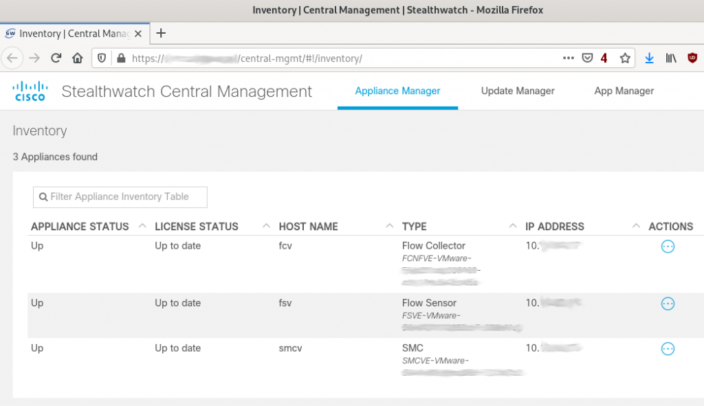
When the certificates of the SMC and the FCNF appliances expired, the configuration/management tunnels, which are SSL connections, stopped working. I still could search flows, receive alarms, etc., but I could not manage the appliances anymore. Basically, the appliance status in the Central Management page of the SMC GUI would say “Management channel down” and have a red dot right next to the status:

For the SMC I could still use the “Edit Applicance Configuration” menu option that one gets by clicking in the “Actions” column, but for the FCNF the option was not even available.

Going to the FCNF appliance GUI to try to configure anything did not work either because, while one can log in, the GUI says that the appliance is managed from Central Management and no options are presented.

So basically absolutely no option to manage in Stealthwatch 7.x an appliance with expired certificates if the appliance is centrally managed. Kind of a Catch-22 situation — Central Management cannot talk to the appliance because the certificate is expired (management channel down), and the appliance GUI says that the appliance is centrally managed and does not allow one to do anything.

After trying lots of things, what worked was the following procedure:

  1. Remove the appliance from Central Management. To do this click on the three dots in the “Actions” menu and select the option “Remove This Appliance”. After this the appliance will not show up in the Central Management page anymore.
  2. For the SMC one is ready to fix the certificate — just go to the appliance management GUI (https://a.b.c.d/smc/index.html) and upload a new certificate via the Configuration -> SSL Certificate screen.
  3. For the other appliances there is an extra step — the appliance still thinks it is centrally managed, so one has to fix that first. The way to do that is to SSH into the appliance (username to use to log in is sysadmin), go to the Advanced menu, and select the option “RemoveAppliance”. After doing this one will be able to browse to the appliance IP address (https://a.b.c.d), log in, and fix the certificate via the Configuration -> SSL Certificate screen.
  4. Now that the certificates are good, the last step is to re-add the appliances to Central Management. That is done using the Appliance Setup Tool (AST) GUI. For non-SMC appliances the link is https://a.b.c.d/swa/loadAst and for an SMC appliance the link is https://a.b.c.d/lc-ast/. The AST will ask for basic configuration parameters, like IP address of the appliance, DNS and NTP servers, etc. It is a wizard-style tool with multiple screens. The AST on the SMC does not ask for the IP address of the SMC (I am guessing it would ask if the SMC is the secondary in a high availability SMC pair) so after running the AST on the SMC one is done and the SMC will now show up in the Central Management page. For the other appliances, however, the last screen of the AST asks for the address of the SMC. Once one provides that IP address and provides the name of the Stealthwatch domain that the appliance is part of the appliance will be added to Central Management and show up in the Central Management page. After a few minutes the status column should show “Up” for the appliance that just got readded to Central Management (see the above screenshot).

The Central Management feature of Stealthwatch 7.x and later is very convinient but it relies heavily on certificates — if certificates are not valid (like trust is not properly configured or certificates have expired) then something is going to break and there is no easy way that I was able to find to fix it.

Note: when adding new identity certificates to the appliances via the appliance management GUI one also needs to set things up so to the appliance can trust the other appliances it will talk to. This is done by making sure that the right certificate is added in the Configuration -> Certificate Authority Certificates screen.

I believe there is room for improvement in how certificates are managed under this central management scheme in Stealthwatch 7.x and later. Hopefully a future Stealthwatch release will make it easier to recover from certificate issues like expired certificates.

In the meantime, do not let your Stealthwatch 7.x and later certificates expire, and if you catch a certificate before it expires and plan to replace it then cross your fingers that the process to renew the certificates through the Central Management GUI works without issues (I did not have a chance to fix my problem that way so I don’t know how well it works).

NetworkManager strongSwan encryption algorithm ‘DES-CBC’ not supported

Recently we ran into an issue involving NetworkManager and strongSwan. The error in the systemd journal was a cryptic “encryption algorithm ‘DES-CBC’ not supported”, as shown in the following log excerpt:

Jul 19 19:14:00 el-valle NetworkManager[733]:  [1532042040.2613] audit: op="connection-activate" uuid="26f20e51-92ba-4a78-a1>
[...]
Jul 19 19:14:00 el-valle NetworkManager[733]:  [1532042040.2764] vpn-connection[0x56050004c1f0,26f20e51-92ba-4a78-a17e-1709b>
Jul 19 19:14:00 el-valle charon-nm[17026]: 05[ASN] encryption algorithm 'DES-CBC' not supported
Jul 19 19:14:00 el-valle charon-nm[17026]: 05[LIB] building CRED_PRIVATE_KEY - RSA failed, tried 8 builders
Jul 19 19:14:00 el-valle NetworkManager[733]:  [1532042040.2862] vpn-connection[0x56050004c1f0,26f20e51-92ba-4a78-a17e-1709b>
Jul 19 19:14:00 el-valle charon-nm[17026]: 05[CFG] received initiate for NetworkManager connection Acme strongSwan
Jul 19 19:14:00 el-valle charon-nm[17026]: 05[CFG] using CA certificate, gateway identity 'vpn.acme.com'
Jul 19 19:14:00 el-valle charon-nm[17026]: 05[ASN] encryption algorithm 'DES-CBC' not supported
Jul 19 19:14:00 el-valle charon-nm[17026]: 05[LIB] building CRED_PRIVATE_KEY - ANY failed, tried 7 builders

In the end we tracked this down to strongSwan being unable to read a private key that had been encrypted with DES. The solution was to re-encrypt the private key using AES-256:

shell$ sudo openssl rsa -in client_key.pem -aes256 -out newkey.pem
Enter pass phrase for client_key.pem:
writing RSA key
Enter PEM pass phrase:
Verifying - Enter PEM pass phrase:
shell$ sudo mv newkey.pem client_key.pem

The following post was helpful to figure out what was happening:

https://lists.strongswan.org/pipermail/users/2017-June/011088.html

Site-to-site VPN Between Cisco ASA/FTD and strongSwan

I recently wasted about two days to bring up a simple site-to-site IPsec VPN tunnel between a Cisco ASA and Cisco FTD and a Linux machine running strongSwan and using digital certificates to authenticate the peers. The configuration was simple but due to a little “detail” and to a lack of good debugging information on the Cisco ASA/FTD, what should have been a five-minute job ended up taking a couple of days of troubleshooting, looking at the strongSwan source code, and making configuration changes to try to make it work. In the end I was able to bring up the tunnel and I got to the bottom of what the Cisco ASA/FTD was not liking from what strongSwan was sending. I will document here the configurations, and finally, at the end, will show what the Cisco ASA/FTD was choking on.

Cisco ASA Configuration

The basic VPN configuration on the Cisco ASA side looks like this:

access-list traffic-to-encrypt extended permit ip 10.123.0.0 255.255.255.0 10.123.1.0 255.255.255.0 
!
crypto ipsec ikev2 ipsec-proposal IPSEC-PROPOSAL
 protocol esp encryption aes-256
 protocol esp integrity sha-256 sha-1
!
crypto map MYMAP 10 match address traffic-to-encrypt
crypto map MYMAP 10 set peer 10.118.57.149 
crypto map MYMAP 10 set ikev2 ipsec-proposal IPSEC-PROPOSAL
crypto map MYMAP 10 set trustpoint TRUSTPOINT chain
!
crypto map MYMAP interface outside
!
crypto ca trustpoint TRUSTPOINT
 revocation-check crl
 keypair TRUSTPOINT
 crl configure
 policy static
 url 1 http://www.chapus.net/ChapulandiaCA.crl
!
crypto ikev2 policy 10
 encryption aes-256
 integrity sha256
 group 14
 prf sha
 lifetime seconds 86400
!
crypto ikev2 enable outside
!
tunnel-group 10.118.57.149 type ipsec-l2l
tunnel-group 10.118.57.149 ipsec-attributes
 ikev2 remote-authentication certificate
 ikev2 local-authentication certificate TRUSTPOINT

Note that the FTD configuration is very similar, but it has to be performed via the Firepower Management Center (FMC) GUI. In fact, after doing the configuration via FMC one can log into the FTD CLI using SSH and run the command “show running-config” and see the same configuration shown above for the ASA.

strongSwan Configuration (ipsec.conf)

The ipsec.conf configuration file (typically located at /etc/ipsec.conf) is the old way of configuring the strongSwan IPsec subsystem. The following ipsec.conf file contents allowed the tunnel to come up with no problems:

config setup
	strictcrlpolicy=yes
	cachecrls = yes

ca MyCA
	crluri = http://www.example.com/MyCA.crl
	cacert = ca.pem
	auto = add

conn %default
	ikelifetime=60m
	keylife=20m
	rekeymargin=3m
	keyingtries=1
	keyexchange=ikev2
	mobike=no

conn net-net
	leftcert=rpi.pem
	leftsubnet=10.123.1.0/24
	leftfirewall=yes
	right=10.122.109.113
	rightid="C=US, ST=CA, L=SF, O=Acme, OU=CSS, CN=asa, E=admin@example.com"
	rightsubnet=10.123.0.0/24
	auto=add

In addition to the ipsec.conf file, the ipsec.secrets (typically /etc/ipsec.secrets) also has to be edited, in this case to indicate the name of the private RSA key. Our ipsec.secrets file looks like this:

# ipsec.secrets - strongSwan IPsec secrets file

: RSA mykey.pem

Finally, certain certificates and the RSA key must be placed (all in PEM format) in certain directories under /etc/ipsec.d:

The Linux machine’s identity certificate goes into /etc/ipsec.d/cert/. strongSwan automatically loads that certificate upon startup
The Certification Authority (CA) root certificate goes into /etc/ipsec.d/cacerts/
The private key must be placed in /etc/ipsec.d/private/

strongSwan Configuration (swanctl.conf)

swanctl.conf is a new configuration file that is used by the swanctl(8) tool to load configurations and credentials into the strongSwan IKE daemon. This is the “new” way to configure the strongSwan IPsec subsystem. The configuration file syntax is very different, though the parameters that need to be set to be able to bring up the IPsec tunnel are the same as in the case of the ipsec.conf-based configuration.

A swanctl.conf-based configuration is more modular. Configuration files typically exist under /etc/swanctl/. For our specific connection, we put the configuration in the file /etc/swanctl/conf.d/example.conf, which gets included from /etc/swanctl/swanctl.conf. Our /etc/swanctl/example.conf file contains the following:

connections {

    # Section for an IKE connection named .
    my-connection {
        # IKE major version to use for connection.
        version = 2

        # Remote address(es) to use for IKE communication, comma separated.
        # remote_addrs = %any
	remote_addrs = 10.122.109.113

        # Section for a local authentication round.
        local-1 {
            # Comma separated list of certificate candidates to use for
            # authentication.
            certs = rpi.pem
        }

        children {

            # CHILD_SA configuration sub-section.
            my-connection {
                # Local traffic selectors to include in CHILD_SA.
                # local_ts = dynamic
                local_ts = 10.123.1.0/24

                # Remote selectors to include in CHILD_SA.
                # remote_ts = dynamic
		remote_ts = 10.123.0.0/24
            }
        }
    }
}

# Section defining secrets for IKE/EAP/XAuth authentication and private key
# decryption.
secrets {
    # Private key decryption passphrase for a key in the private folder.
    private-rpikey {
        # File name in the private folder for which this passphrase should be
        # used.
        file = rpi.pem

        # Value of decryption passphrase for private key.
        # secret =
    }
}

# Section defining attributes of certification authorities.
authorities {
    # Section defining a certification authority with a unique name.
    MyA {
        # CA certificate belonging to the certification authority.
        cacert = myca.pem

        # Comma-separated list of CRL distribution points.
        crl_uris = http://www.chapus.net/ChapulandiaCA.crl
    }
}

Bringing Up the Tunnel on Interesting Traffic

To bring up the tunnel when “interesting” traffic is received it is necessary to use the “start_action” configuration parameter. Otherwise the IPsec tunnel has to be brought up manually using the swanctl –initiate xxxxx command.

Here’s an example configuration that uses “start_action”:

connections {

# Section for an IKE connection named <conn>.
 lab-vpn {
 version = 2

 remote_addrs = 10.1.10.114

 local-1 {
 certs = rpi.pem
 }

children {
 # CHILD_SA configuration sub-section.
 lab-vpn {
 local_ts = 10.123.1.0/24, 10.10.0.0/16
 remote_ts = 10.123.0.0/24

start_action = trap
 }
 }
 }

}

Automatically Starting Charon

The charon-systemd daemon implements the IKE daemon very similar to charon, but is specifically designed for use with systemd. It uses the systemd libraries for a native integration and comes with a simple systemd service file.

In vesions of strongSwan prior to 5.8.0 one needed to enable the systemd service “strongswan-swanctl”. In versions 5.8.0 and later it is now “strongswan”.

To start the charon-systemd daemon when the system boots just use systemctl to enable the service:

systemctl enable strongswan

Reference: https://wiki.strongswan.org/projects/strongswan/wiki/Charon-systemd

Issues

There were three serious issues that I ran into when trying to bring up the site to site tunnel. All of them appear to be bugs.

Cisco ASA/FTD Unable to Process Downloaded CRL When Cisco WSA in the Middle

In this issue the Cisco ASA/FTD is apparently unable to parse a downloaded CRL when a Cisco WSA proxy server is transparently in the middle. The Cisco WSA is returning the file to the Cisco ASA/FTD but the ASA apparently does not like something in the HTTP headers (the “Via” header? I don’t know). There is nothing wrong with the CRL itself — I performed a packet capture on the ASA itself, extracted the CRL file from the packet capture, and it is not corrupted or anything. In fact, I have seen the revocation check work sometimes; I believe the problem occurs when the CRL is present in the WSA’s cache, which would explain why it works sometimes. I configured the web server hosting the CRL to prevent caching of the file but the problem still persists.

Workaround for this problem: Configure the ASA to fallback to no revocation check, i.e.

crypto ca truspoint X
 revocation-check crl none

PRF Algorithms Other Than SHA1 Do Not Work

No idea if the problem here is on the Cisco ASA/FTD side or on the strongSwan side. All I know is that strongSwan fails to authenticate the peer. I see these messages in the strongSwan logs:

[ENC] parsed IKE_AUTH response 1 [ V IDr CERT AUTH SA TSi TSr N(ESP_TFC_PAD_N) N(NON_FIRST_FRAG) N(MOBIKE_SUP) ]
[IKE] received end entity cert ""
[CFG]   using certificate ""
[CFG]   using trusted ca certificate ""
[CFG] checking certificate status of ""
[CFG]   using trusted certificate ""
[CFG]   crl correctly signed by ""
[CFG]   crl is valid: until Jan 06 02:12:01 2018
[CFG]   using cached crl
[CFG] certificate status is good
[CFG]   reached self-signed root ca with a path length of 0
[IKE] signature validation failed, looking for another key
[ENC] generating INFORMATIONAL request 2 [ N(AUTH_FAILED) ]
[NET] sending packet: from 10.118.57.151[4500] to 10.122.109.113[4500] (80 bytes)
initiate failed: establishing CHILD_SA 'css-lab' failed

Workaround for this problem: Use SHA-1 as the PRF. For example, on the ASA, one could use:

crypto ikev2 policy 10
 encryption aes-256
 integrity sha256
 group 19
 prf sha

Certificates Using ASN.1 “PRINTABLESTRING” Don’t Work on Cisco ASA/FTD

This one was very difficult to troubleshoot. It might be a bug on the strongSwan side but I am not sure. The issue is that, depending on configuration, strongSwan will use as IKEv2 identity to send to the Cisco ASA/FTD a Distinguished Name (DN) in binary ASN.1 encoding, but when it creates this binary ASN.1 encoding it will use the type “PRINTABLESTRING” instead of “UTF8STRING” to represent fields like Country, stateOrProvince, localityName, organizationName, commonName, etc. The IKEv2 identity is otherwise identical to the identity that strongSwan would obtain directly from the certificate.

On the ASA/FTD side, when the ASA/FTD receives an identity that uses fields of type “PRINTABLESTRING” it seems to consider the identity bad, and it chokes. This is made difficult to troubleshoot by the fact that there apparently are no good debug messages to see what is going on. On a bad case one sees these messages:

%ASA-7-711001: IKEv2-PLAT-3: RECV PKT [IKE_AUTH] [10.118.57.149]:500->[10.122.109.113]:500 InitSPI=0x596a08fccb72412a RespSPI=0x5d757649514ab5e8 MID=00000001
%ASA-7-711001: (34):  
%ASA-7-711001: IKEv2-PROTO-2: (34): Received Packet [From 10.118.57.149:500/To 10.122.109.113:500/VRF i0:f0] 
[...]
%ASA-7-711001:  IDr%ASA-7-711001:   Next payload: CERT, reserved: 0x0, length: 128
%ASA-7-711001:     Id type: DER ASN1 DN, Reserved: 0x0 0x0
%ASA-7-711001: 
%ASA-7-711001:      30 76 31 0b 30 09 06 03 55 04 06 13 02 55 53 31
%ASA-7-711001:      0b 30 09 06 03 55 04 08 13 02 4e 43 31 0c 30 0a
%ASA-7-711001:      06 03 55 04 07 13 03 52 54 50 31 0e 30 0c 06 03
%ASA-7-711001:      55 04 0a 13 05 43 69 73 63 6f 31 0c 30 0a 06 03
%ASA-7-711001:      55 04 0b 13 03 43 53 53 31 0c 30 0a 06 03 55 04
%ASA-7-711001:      03 13 03 72 70 69 31 20 30 1e 06 09 2a 86 48 86
%ASA-7-711001:      f7 0d 01 09 01 16 11 65 6c 70 61 72 69 73 40 63
%ASA-7-711001:      69 73 63 6f 2e 63 6f 6d
[...]
%ASA-7-711001: IKEv2-PROTO-5: (34): SM Trace-> SA: I_SPI=596A08FCCB72412A R_SPI=5D757649514AB5E8 (I) MsgID = 00000001 CurState: I_WAIT_AUTH Event: EV_RECV_AUTH
%ASA-7-711001: IKEv2-PROTO-5: (34): Action: Action_Null
%ASA-7-711001: IKEv2-PROTO-5: (34): SM Trace-> SA: I_SPI=596A08FCCB72412A R_SPI=5D757649514AB5E8 (I) MsgID = 00000001 CurState: I_PROC_AUTH Event: EV_CHK4_NOTIFY
%ASA-7-711001: IKEv2-PROTO-2: (34): Process auth response notify
%ASA-7-711001: IKEv2-PROTO-5: (34): SM Trace-> SA: I_SPI=596A08FCCB72412A R_SPI=5D757649514AB5E8 (I) MsgID = 00000001 CurState: I_PROC_AUTH Event: EV_PROC_MSG
%ASA-7-711001: IKEv2-PLAT-2: (34): peer auth method set to: 1
%ASA-7-711001: IKEv2-PROTO-5: (34): SM Trace-> SA: I_SPI=596A08FCCB72412A R_SPI=5D757649514AB5E8 (I) MsgID = 00000001 CurState: I_WAIT_AUTH Event: EV_RE_XMT
%ASA-7-711001: IKEv2-PROTO-2: (34): Retransmitting packet
%ASA-7-711001: (34):  
%ASA-7-711001: IKEv2-PROTO-2: (34): Sending Packet [To 10.118.57.149:500/From 10.122.109.113:500/VRF i0:f0] 

As can be seen, the state machine goes from I_WAIT_AUTH (wait for authentication payload) to I_PROC_AUTH (process authentication payload), receives an “EV_PROC_MSG” (process message event), and then goes back to the I_WAIT_AUTH state with a retransmit (EV_RE_XMT) event. There is not explanation or message that indicates why process the IKEv2 identity failed.

In the good case, when see messages like:

%ASA-7-711001: IKEv2-PROTO-5: (35): SM Trace-> SA: I_SPI=03542332E12C42F4 R_SPI=3E95373B6C8C25AF (I) MsgID = 00000001 CurState: I_WAIT_AUTH Event: EV_RECV_AUTH
%ASA-7-711001: IKEv2-PROTO-5: (35): Action: Action_Null
%ASA-7-711001: IKEv2-PROTO-5: (35): SM Trace-> SA: I_SPI=03542332E12C42F4 R_SPI=3E95373B6C8C25AF (I) MsgID = 00000001 CurState: I_PROC_AUTH Event: EV_CHK4_NOTIFY
%ASA-7-711001: IKEv2-PROTO-2: (35): Process auth response notify
%ASA-7-711001: IKEv2-PROTO-5: (35): SM Trace-> SA: I_SPI=03542332E12C42F4 R_SPI=3E95373B6C8C25AF (I) MsgID = 00000001 CurState: I_PROC_AUTH Event: EV_PROC_MSG
%ASA-7-711001: IKEv2-PLAT-2: (35): peer auth method set to: 1
%ASA-7-711001: IKEv2-PROTO-5: (35): SM Trace-> SA: I_SPI=03542332E12C42F4 R_SPI=3E95373B6C8C25AF (I) MsgID = 00000001 CurState: I_PROC_AUTH Event: EV_CHK_IF_PEER_CERT_NEEDS_TO_BE_FETCHED_FOR_PROF_SEL
%ASA-7-711001: IKEv2-PROTO-5: (35): SM Trace-> SA: I_SPI=03542332E12C42F4 R_SPI=3E95373B6C8C25AF (I) MsgID = 00000001 CurState: I_PROC_AUTH Event: EV_GET_POLICY_BY_PEERID

Notice that after the EV_PROC_MSG event there is no re-transmit event — in the logs I could see that eventually (after checking revocation of the certificate, etc.) the state machine leaves the I_PROC_AUTH state and the connection finally establishes.

The strongSwan configuration that caused the above problem was specifying “leftid” in /etc/ipsec.conf, i.e.

conn net-net
	leftcert=rpi.pem
	leftsubnet=10.123.1.0/24
	leftid="C=US, ST=CA, L=SF, O=Acme, OU=CSS, CN=myid, E=admin@example.com"
	leftfirewall=yes
	right=10.122.109.113
	rightid="C=US, ST=CA, L=SF, O=Acme, OU=CSS, CN=asa, E=admin@example.com"

If leftid is removed, and strongSwan is left to automatically detect the identity to send to the Cisco ASA/FTD then the problem does not occur. I think it is because it does not create the ID from scratch but instead extracts it from the identity certificate.

Here’s a diff of the output from “openssl asn1” for the case of the IKEv2 ID using an ASN.1 binary encoding that has “UTF8STRING” fields, and for the case where “PRINTABLESTRING” are used:

    15:d=1  hl=2 l=  11 cons: SET               
    17:d=2  hl=2 l=   9 cons: SEQUENCE          
    19:d=3  hl=2 l=   3 prim: OBJECT            :stateOrProvinceName
-   24:d=3  hl=2 l=   2 prim: UTF8STRING        :CA
+   24:d=3  hl=2 l=   2 prim: PRINTABLESTRING   :CA
    28:d=1  hl=2 l=  12 cons: SET               
    30:d=2  hl=2 l=  10 cons: SEQUENCE          
    32:d=3  hl=2 l=   3 prim: OBJECT            :localityName
-   37:d=3  hl=2 l=   3 prim: UTF8STRING        :SF
+   37:d=3  hl=2 l=   3 prim: PRINTABLESTRING   :SF
    42:d=1  hl=2 l=  14 cons: SET               
    44:d=2  hl=2 l=  12 cons: SEQUENCE          
    46:d=3  hl=2 l=   3 prim: OBJECT            :organizationName
-   51:d=3  hl=2 l=   5 prim: UTF8STRING        :Acme
+   51:d=3  hl=2 l=   5 prim: PRINTABLESTRING   :Acme
    58:d=1  hl=2 l=  12 cons: SET               
    60:d=2  hl=2 l=  10 cons: SEQUENCE          
    62:d=3  hl=2 l=   3 prim: OBJECT            :organizationalUnitName
-   67:d=3  hl=2 l=   3 prim: UTF8STRING        :CSS
+   67:d=3  hl=2 l=   3 prim: PRINTABLESTRING   :CSS
    72:d=1  hl=2 l=  12 cons: SET               
    74:d=2  hl=2 l=  10 cons: SEQUENCE          
    76:d=3  hl=2 l=   3 prim: OBJECT            :commonName
-   81:d=3  hl=2 l=   3 prim: UTF8STRING        :rpi
+   81:d=3  hl=2 l=   3 prim: PRINTABLESTRING   :rpi
    86:d=1  hl=2 l=  32 cons: SET               
    88:d=2  hl=2 l=  30 cons: SEQUENCE          
    90:d=3  hl=2 l=   9 prim: OBJECT            :emailAddress

Workaround for this issue: Do not use leftid and let strongSwan figure out the IKEv2 ID that it needs to present to the Cisco ASA/FTD.

Multiple Traffic Selectors Under Same Child SA

If the strongSwan configuration specifies multiple networks in one traffic selector, like in this configuration:

children {
 # CHILD_SA configuration sub-section.
 lab-vpn {
 # Local traffic selectors to include in CHILD_SA.
 # local_ts = dynamic
 local_ts = 10.123.1.0/24, 10.10.0.0/16

# Remote selectors to include in CHILD_SA.
 # remote_ts = dynamic
 remote_ts = 10.123.0.0/24
 }
 }

then the Cisco device will receive a TSi and TSr payloads in an IKEv2 message that look like these:

 TSi Next payload: TSr, reserved: 0x0, length: 56
 Num of TSs: 3, reserved 0x0, reserved 0x0
 TS type: TS_IPV4_ADDR_RANGE, proto id: 1, length: 16
 start port: 2048, end port: 2048
 start addr: 10.123.1.2, end addr: 10.123.1.2
 TS type: TS_IPV4_ADDR_RANGE, proto id: 0, length: 16
 start port: 0, end port: 65535
 start addr: 10.123.1.0, end addr: 10.123.1.255
 TS type: TS_IPV4_ADDR_RANGE, proto id: 0, length: 16
 start port: 0, end port: 65535
 start addr: 10.10.0.0, end addr: 10.10.255.255
 TSr Next payload: NOTIFY, reserved: 0x0, length: 40
 Num of TSs: 2, reserved 0x0, reserved 0x0
 TS type: TS_IPV4_ADDR_RANGE, proto id: 1, length: 16
 start port: 2048, end port: 2048
 start addr: 10.123.0.5, end addr: 10.123.0.5
 TS type: TS_IPV4_ADDR_RANGE, proto id: 0, length: 16
 start port: 0, end port: 65535
 start addr: 10.123.0.0, end addr: 10.123.0.255

As can be seen, the TSi payload contains multiple Traffic Selectors (one for 10.123.1.0/24 and another one for 10.10.0.0/16). This is based on the strongSwan configuration “local_ts = 10.123.1.0/24, 10.10.0.0/16”.

The idea is that the IPsec gateway that strongSwan is talking to should create IPsec Security Associations (SAs) for 10.123.1.0/24 <-> 10.123.0.0 and for 10.10.0.0/16 <-> 10.123.0.0.

Unfortunately, Cisco devices do not support this and instead only create SAs for the first traffic selector in the IKE message. There is a Cisco bug for this issue on Cisco ASA, but it does not appear that it will be fixed any time soon (as of May 2018):

CSCue42170 (“IKEv2: Support Multi Selector under the same child SA”)

strongSwan users have reported the problem:

https://wiki.strongswan.org/issues/758

A workaround has been proposed here. The workaround consists of creating multiple connections, one for each protect netowrk, instead of one connection with multiple protected networks.

Static CRL Revocation Check No Longer Works

If you had configuration like this before ASA 9.13.1:

crypto ca trustpoint <trustpoint>
 crl configure
  policy static
  url 1 http://x

then that will no longer work as the “url” command has been removed in ASA Software version 9.13.1 and later. The new way to configure the same thing is:

crypto ca certificate map <map> 10
 issuer-name attr cn co <cn> issuing
 issuer-name attr dc eq <dc>

crypto ca trustpoint <trustpoint>
 match certificate <map> override cdp 1 url http://x
 crl configure
 policy static

but it requires ASA versions 9.13.1.12 or later, or 9.14.1.12 or later.

This is tracked by Cisco bug ID CSCvu05216 (“cert map to specify CRL CDP Override does not allow backup entries”).

The removal of the “url” command is documented in the ASA Software 9.13 release notes under “Important Notes”:

https://www.cisco.com/c/en/us/td/docs/security/asa/asa913/release/notes/asarn913.html#reference_yw3_ngz_vhb

“Removal of CRL Distribution Point commands—The static CDP URL configuration commands, namely crypto-ca-trustpoint crl and crl url were removed with other related logic.

Note: The CDP URL configuration option was restored later (refer CSCvu05216).”

Conclusion

A site-to-site IPsec-based VPN tunnel between Cisco ASA/FTD and strongSwan running on Linux and using certificates for authentication comes up just fine but I ran into the three issues described above. All issues have reasonable workarounds. They are probably bugs that I’ll try to report to the respective parties.

SSL Certificates Made Easy (and Cheap!)

Running an SSL-enabled website is a best practice but often made difficult by the fact that one needs a Private Key Infrastructure (PKI) to obtain the SSL certificates needed for SSL operation.

There are two options for using a PKI: 1. Deploy your own PKI, and 2. Use a public PKI. The former is cheap (free) but has a steeper learning curve because one needs to know how to set up the Certification Authority (CA) server software and how to manage the PKI (generate Certificate Signing Requests [CSRs], sign certificates, revoke certificates, deploy the root CA certificate to endusers’ devices, etc.). The latter can be non-free but is easier as the PKI is already established and one only needs to request a certificate, sometimes for a price.

The Let’s Encrypt project is “[…] a free, automated, and open certificate authority (CA), run for the public’s benefit. It is a service provided by the Internet Security Research Group (ISRG).” See https://letsencrypt.org/about/ for additional details about the Let’s Encrypt project. Two important details about certificates issued by the Let’s Encrypt project is that: 1. They are free, and 2. Browsers trust the CA that issues them, so there is no need to distribute CA root certificates to endusers’ devices.

We run an Apache web server that serves a few domains via virtual hosts and it was easy to set them up to use certificates issued by the Let’s Encrypt project. Here are the details:

We run Apache on Ubuntu so the first thing we had to do was to install an ACME client (ACME is a protocol used to fetch certificates). The ACME client recommended by the Let’s Encrypt project is called Certbot. According to the Certbot’s website, “Certbot is an easy-to-use automatic client that fetches and deploys SSL/TLS certificates for your webserver. Certbot was developed by EFF and others as a client for Let’s Encrypt and was previously known as “the official Let’s Encrypt client” or “the Let’s Encrypt Python client.” Certbot will also work with any other CAs that support the ACME protocol”.

The Certbot website has clear instructions on how to do this. For us, it was just:

shell$ sudo add-apt-repository ppa:certbot/certbot
shell$ sudo apt-get update
shell$ sudo apt-get install certbot

The next step was to request the certificates. There are Certbot “plugins” that automate the process but we chose a very manual process that gives us a little bit more control over the entire process:

shell$ sudo certbot certonly --webroot -w /srv/www/www.domain1.net/ -d domain1.net -d www.domain1.net -w /usr/share/wordpress -d www.domain2.com -d domain2.com
 Saving debug log to /var/log/letsencrypt/letsencrypt.log
 Starting new HTTPS connection (1): acme-v01.api.letsencrypt.org

-------------------------------------------------------------------------------
 You have an existing certificate that contains a portion of the domains you
 requested (ref: /etc/letsencrypt/renewal/www.domain1.net.conf)

It contains these names: www.domain1.net, domain1.net

You requested these names for the new certificate: domain1.net, www.domain1.net,
 www.domain2.com, domain2.com.

Do you want to expand and replace this existing certificate with the new
 certificate?
 -------------------------------------------------------------------------------
 (E)xpand/(C)ancel: e
 Renewing an existing certificate
 Performing the following challenges:
 http-01 challenge for domain1.net
 http-01 challenge for www.domain1.net
 http-01 challenge for www.domain2.com
 http-01 challenge for domain2.com
 Using the webroot path /usr/share/wordpress for all unmatched domains.
 Waiting for verification...
 Cleaning up challenges
 Unable to clean up challenge directory /srv/www/www.domain1.net/.well-known/acme-challenge
 Generating key (2048 bits): /etc/letsencrypt/keys/0001_key-certbot.pem
 Creating CSR: /etc/letsencrypt/csr/0001_csr-certbot.pem

IMPORTANT NOTES:
 - Congratulations! Your certificate and chain have been saved at
 /etc/letsencrypt/live/www.domain1.net/fullchain.pem. Your cert will
 expire on 2017-06-26. To obtain a new or tweaked version of this
 certificate in the future, simply run certbot again. To
 non-interactively renew *all* of your certificates, run "certbot
 renew"
 - If you like Certbot, please consider supporting our work by:

Donating to ISRG / Let's Encrypt: https://letsencrypt.org/donate
 Donating to EFF: https://eff.org/donate-le

Note that I had previously requested a certificate for www.domain1.net, and when I ran Certbot I requested a new domain to be listed in the certificate (www.domain2.com). Certbot noticed that I had previously requested a certificate for www.domain1.net and asked me if I wanted to expand the certificate to include the new domain.

As mentioned in the output from the certbot, the certificates (identity certificate for the website as well as the CA certificate) are left in the /etc/letsencrypt/live/www.domain1.net directory. At this point one just has to configure Apache to use these certificates.

Reset Azure Virtual Netwok Gateway

No matter what I did I could not get an IPsec site-to-site tunnel going between an offsite test network and our Microsoft Azure virtual network. Our VPN gateway is a Cisco ASA 5506.

The issue was that the Cisco ASA would try to bring up the tunnel but some part of the negotiation would go wrong at some point. Debug messages on the Cisco ASA would show something like this:

Apr 19 09:21:41 [IKEv1 DEBUG]IP = 13.94.202.38, IKE SA Proposal # 1, Transform # 2 acceptable Matches global IKE entry # 5
 Apr 19 09:21:41 [IKEv1 DEBUG]IP = 13.94.202.38, constructing ISAKMP SA payload
 Apr 19 09:21:41 [IKEv1 DEBUG]IP = 13.94.202.38, constructing NAT-Traversal VID ver RFC payload
 Apr 19 09:21:41 [IKEv1 DEBUG]IP = 13.94.202.38, constructing Fragmentation VID + extended capabilities payload
 Apr 19 09:21:41 [IKEv1]IP = 13.94.202.38, IKE_DECODE SENDING Message (msgid=0) with payloads : HDR + SA (1) + VENDOR (13) + VENDOR (13) + NONE (0) total length : 128
 Apr 19 09:21:42 [IKEv1]IP = 13.94.202.38, Duplicate first packet detected. Ignoring packet.
 Apr 19 09:21:43 [IKEv1]IP = 13.94.202.38, Duplicate first packet detected. Ignoring packet.
 Apr 19 09:21:46 [IKEv1]IP = 13.94.202.38, Duplicate first packet detected. Ignoring packet.
 Apr 19 09:21:49 [IKEv1]IP = 13.94.202.38, IKE_DECODE RESENDING Message (msgid=0) with payloads : HDR + SA (1) + VENDOR (13) + VENDOR (13) + NONE (0) total length : 128
 Apr 19 09:21:57 [IKEv1]IP = 13.94.202.38, IKE_DECODE RESENDING Message (msgid=0) with payloads : HDR + SA (1) + VENDOR (13) + VENDOR (13) + NONE (0) total length : 128
 Apr 19 09:22:05 [IKEv1]IP = 13.94.202.38, IKE_DECODE RESENDING Message (msgid=0) with payloads : HDR + SA (1) + VENDOR (13) + VENDOR (13) + NONE (0) total length : 128
 Apr 19 09:22:13 [IKEv1 DEBUG]IP = 13.94.202.38, IKE MM Responder FSM error history (struct &0x00002aaac1c34cf0) , : MM_DONE, EV_ERROR-->MM_WAIT_MSG3,
 EV_TIMEOUT-->MM_WAIT_MSG3, NullEvent-->MM_SND_MSG2, EV_SND_MSG-->MM_SND_MSG2, EV_START_TMR-->MM_SND_MSG2, EV_RESEND_MSG-->MM_WAIT_MSG3, EV_TIMEOUT-->MM_WAIT_MSG3, NullEvent
 Apr 19 09:22:13 [IKEv1 DEBUG]IP = 13.94.202.38, IKE SA MM:4af079c0 terminating: flags 0x01000002, refcnt 0, tuncnt 0
 Apr 19 09:22:13 [IKEv1 DEBUG]IP = 13.94.202.38, sending delete/delete with reason message
 Apr 19 09:23:06 [IKEv1]IP = 13.94.202.38, IKE_DECODE RECEIVED Message (msgid=6a9f34a4) with payloads : HDR + HASH (8) + DELETE (12) + NONE (0) total length : 68
 Apr 19 09:23:06 [IKEv1 DEBUG]Group = 13.94.202.38, IP = 13.94.202.38, processing hash payload
 Apr 19 09:23:06 [IKEv1 DEBUG]Group = 13.94.202.38, IP = 13.94.202.38, processing delete
 Apr 19 09:23:06 [IKEv1]Group = 13.94.202.38, IP = 13.94.202.38, Connection terminated for peer 13.94.202.38. Reason: Peer Terminate Remote Proxy 10.100.152.0, Local Proxy 10.50.0.0
 Apr 19 09:23:06 [IKEv1 DEBUG]Group = 13.94.202.38, IP = 13.94.202.38, Active unit receives a delete event for remote peer 13.94.202.38.

A couple of key points in the above debug messages:

  1. “MM_WAIT_MSG3, EV_TIMEOUT” indicates that the Cisco ASA timeout waiting for the Azure VPN gateway.
  2. “Duplicate first packet detected. Ignoring packet” indicates that the Azure VPN gateway is not liking the previous message that the Cisco ASA sends. Increasing the debug level (not shown above) indicates a mismatch in terms of cookies, and this is apparently what upsets the Azure Virtual Network Gateway.

This is shown on Cisco ASA debug messages at a higher debug level:

Azure
 InitiatorCookie: 03 83 AD 7C 10 26 CB D6
 ResponderCookie: 14 42 19 27 F6 F2 DF 53

RECV PACKET from 13.91.5.150
 ISAKMP Header
 Initiator COOKIE: 03 83 ad 7c 10 26 cb d6
 Responder COOKIE: 00 00 00 00 00 00 00 00

These are debug messages produced on the Microsoft Azure side:

2016?-?03?-?02 10:31:37 ERROR user NULL 0000000FE1E59D80 0000000FE1E64320 f74513382e60832f cac68571e57c06d5 Invalid cookies. Try resetting SAs on-prem. IkeProcessPacketDispatch failed with HRESULT 0x80073616(ERROR_IPSEC_IKE_INVALID_COOKIE)

(Note the “ERROR_IPSEC_IKE_INVALID_COOKIE” error code.)

After spending sometime troubleshooting the Cisco ASA side we could not find anything wrong with the Cisco ASA configuration.

In the end, in my desperation, I decided to reset the Azure Virtual
Network Gateway and that seems to have fixed the issue for good.

The process to reset an Azure Virtual Network Gateway is a bit tricky because there is no way to do that using the Azure Portal; it needs to be done using PowerShell instead.

This is what I did to reset the Azure Virtual Network Gateway using
PowerShell:

1. Install Azure PowerShell. I used the instructions here:

https://azure.microsoft.com/en-us/documentation/articles/powershell-install-configure/

In particular, I went with the leaner and perhaps more complicated
installation from the PowerShell Gallery (instead of installing from
WebPI).

2. After Azure PowerShell was installed, I opene a PowerShell command window and ran the following commands:

Login-AzureRmAccount
Select-AzureRmSubscription -SubscriptionName "<your subscription name>"
$vg = Get-AzureRmVirtualNetworkGateway -ResourceGroupName RG
Reset-AzureRmVirtualNetworkGateway -VirtualNetworkGateway $vg

Apparently, Azure Virtual Network Gateways are redundant Virtual Machines so resetting one will cause the other to take over.

The other one could be reset by invoking “Reset-AzureRmVirtualNetworkGateway” a few minutes after the first gateway has been reset but in my case the site-to-site VPN tunnel came up after resetting only one of the gateways.

Note that the above XXXXX-AzureRmXXXXX PowerShell cmdlets use the new
Azure Resource Manager deployment model. Similar commands would have to
be used if the classic deployment model is used instead.

This article:

https://azure.microsoft.com/en-us/documentation/articles/vpn-gateway-resetgw-classic/

is a good reference for how to reset Azure Virtual Network Gateways that have been deployed using the classic deployment model. Note that it says that the same cannot be done for the Resource Manager deployment model but I think the capability is there now (I used it) and it is just that the article has not been updated yet.

On a related note, I should mention that another way of dealing with this problem is by deploying a Cisco ASAv virtual appliance and using that to terminate the site-to-site IPsec tunnel instead of terminating it on the Microsoft-provided Azure Virtual Network Gateway. This of course would be more expensive given that licenses for the Cisco ASAv would have to be purchased, plus it is another Virtual Machine that would have to deployed (and pay for).

SSL Traffic Decryption

We recently had a need to inspect the contents of an HTTPS (SSL/TLS) connection. As we had never had the opportunity to set things up to facilitate decryption of SSL/TLS connection we had to do a little bit of research.

The way we approached this was by running the software that establishes the HTTPS connection we need to decrypt on a VirtualBox Virtual Machine (VM), and then running a Man-in-the-Middle (MitM) proxy on the VM host, which runs Ubuntu 15.04. The MitM proxy that we used was mitmproxy. No reason in particular for choosing mitmproxy other than it was the first solution that we tried, it was very well documented, and it worked on first try. We are very impressed with this little piece of software — its design is well thought, and the text-based user interface is very powerful.

This post documents the steps involved in setting things up for decryption of SSL sessions.

General

There are several possible network topologies to use. The one that we chose was one where the client machine and the proxy machine are on the same physical network. Because we are using VirtualBox, where the Virtual Machine is the client machine and the Virtual Machine host is a physical machine, we configured the network settings of the (client) Virtual Machine to use bridged networking. This is equivalent to having two different machines on the same physical network segment.

Note: Our proxy machine (not a Virtual Machine) only had a wi-fi network interface so the Virtual Machine, through bridged networking, was using this wi-fi network interface to reach the network.

Set Up Of Proxy Machine

Installation

Nothing much to do here, really, as there is an Ubuntu binary package for mitmproxy, so installation boils down to a simple “apt-get install mitmproxy”.

VirtualBox Settings

The network interface of the virtual machine must be configured in bridged mode. The VM host machine only needs one interface (for example, the wireless NIC “wlan0”). That interface will be used for both the VM host and the actual VM to have network connectivity. Make sure the VM NIC is configured to use the VM host NIC as the bridge interface.

Also, VirtualBox must be configured to allow promiscuous mode on the bridge interface. This is configured in the “Advanced” section of the network adapter properties (where the interface mode [bridged, NAT, etc.] is configured). “Allow VMs” for the “Promiscuous Mode” setting is appropriate.

Configuration

After installing the mitmproxy software, the following things must be done:

  • Enable IP forwarding, which is normally disabled by default:
shell$ sudo sh -c 'echo 1 > /proc/sys/net/ipv4/ip_forward'
  • Disable ICMP redirects:
shell$ sudo sh -c 'echo 0 > /proc/sys/net/ipv4/conf/all/send_redirects'
shell$ sudo sh -c 'echo 0 > /proc/sys/net/ipv4/conf/wlan0/send_redirects'
  • Add iptables rules to redirect traffic going to destination TCP port 443 to port 8080, which is where mitmproxy is listening on:
shell$ sudo iptables -t nat -A PREROUTING -i wlan0 -p tcp --dport 80 -j REDIRECT --to-port 8080
shell$ sudo iptables -t nat -A PREROUTING -i wlan0 -p tcp --dport 443 -j REDIRECT --to-port 8080
  • Run mitmproxy:
shell$ mitmproxy -T --host

Setup Of Client Machine

The following things need to be configured on the client machine:

  • Configure the machine running mitmproxy (the proxy machine) as the default gateway. This will cause all SSL/TLS traffic going towards the server to be sent through the proxy machine, assuming that the server is on a different (remote) subnet.
  • Install the Certificate Authority certificate that the proxy machine will present to the client when the client establishes SSL/TLS sessions. mitmproxy really shines in this area, making the certificate installation a very seamless process. We will not repeat here the excellent documentation on how to do this. Instead, we will point readers to the documentation: http://mitmproxy.org/doc/certinstall.html.
  • The default gateway of the client machine must obviously be the proxy machine. The easiest way to accomplish this is by configuring manually the TCP/IP settings of the client machine. If DHCP is used for IP configuration then the default gateway will be whatever the DHCP sends, which might be different from the IP address of the proxy machine. In that case the client machine can be forced to use the proxy machine as its default gateway by adding a new default route using a lower metric, for example: ip route add default via <IP address of proxy machine> metric 50.

Decrypting The SSL/TLS Session

Once the machine running the mitmproxy software (the “proxy” machine) and the machine running the SSL/TLS client (the “client” machine) are configured, we are ready to establish the SSL/TLS sessions that we want to decrypt — just open your browser and go to the https:// URL you are interested in examining, launch your SSL VPN client, etc.

The proxy machine will intercept the connection and do what it does well, i.e. pretend to the server to be the client, and pretend to the client to be the server, while decrypting traffic going in both directions.

mitmproxy provides a fantastic text-based user interface that allows the user to easily navigate through each SSL/TLS request and response going through the proxy.

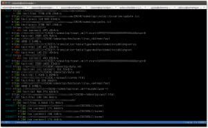
The following screenshot (click on image for larger version) shows the main mitmproxy window, which lists all the captured flows:

mitmproxy1

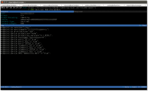
The following screenshot (click on image for larger version) shows a particular flow, especifically the request part of the flow:

mitmproxy2

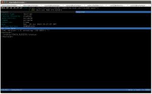
And finally, this screenshot (click on image for larger version) shows the server’s response to the previous request:

mitmproxy3

And that is it; there really isn’t anything to it. It took longer to read the mitmproxy documentation than to set things up and run the SSL/TLS session.

Final Thoughts

From the main mitmproxy window, all flows can be saved to a file for later analysis by pressing the ‘w’ (write) key, which will prompt if all flows must be saved or just the one at the cursor, and the name of the file to save the flows to.

Flows can be loaded later by running mitmproxy with the -r (read) switch.

 Caveats

Be aware of mitmproxy bug 659 (https://github.com/mitmproxy/mitmproxy/issues/659). This bug causes HTTP HEAD requests to return a Content-Length equal to zero instead of the correct value. This will cause some applications to fail as they will think there is nothing to download. This trip me up pretty good until I found the previously mentioned bug and I applied the fix that was committed to resolve the bug.


More GNOME/Ubuntu Unity System-wide Defaults

In this post we discussed how to set up system-wide defaults using GSettings schema overrides. This works great but we recently ran into a situation where this was not possible because the schema we wanted to modify was “relocatable”. Trying to modify such a schema without specifying a DConf path results in the following error:

$ gsettings set org.compiz.opengl sync-to-vblank true
Schema 'org.compiz.opengl' is relocatable (path must be specified)

The correct way to change a relocatable schema is by appending the path, as the error message above states. For example:

$ gsettings get org.compiz.opengl:/apps/compiz-1/plugins/opengl/screen0/options/sync_to_vblank/ sync-to-vblank
true

(Note the “:/apps/compiz-1/plugins/opengl/screen0/options/sync_to_vblank/ after the schema name; this is the path to the preference.)

The problem with this approach is that either by design or because it is a bug, it is not possible to write a schema override file that includes a DConf path. This Ubuntu bug seems to imply that this is a bug.

Another way to accomplish a system-wide default is by going to a lower level than GSettings and configuring DConf directly. It is probably better to use GSettings but in this particular case we had no option.

Here’s what we did:

First, we created the file /etc/dconf/profile/user with the following contents:

user-db:user
system-db:system-wide

Next, we created the directory /etc/dconf/db/system-wide.d and the file /etc/dconf/db/system-wide.d/00_compiz_site_settings with the following contents:

[org/compiz/profiles/unity/plugins/opengl]
enable-x11-sync=false

We then ran the command “dconf update” (as root) which created the DConf database /etc/dconf/db/system-wide (a binary file).

This causes the “opengl” Compiz plugin preference “enable-x11-sync” to be set to “false” for all users in the system.

References

This blog post from Ross Burton has a good discussion on how to set system-wide settings using GSettings: http://www.burtonini.com/blog/computers/gsettings-override-2011-07-04-15-45. It would have been a good reference to provide in my previous post but we missed it when we wrote that post.

The dconf System Administrator Guide is a fantastic reference to understand how to set system-wide defaults using DConf. One thing that was not clear to use after reading this document was that of DConf profile selection — the explanation above uses the file /etc/dconf/profiles/user because if no other DConf profile is selected (via the DCONF_PROFILE environment variable) then the profile called “user” is the one that is opened.

This post by Matt Fischer was extremely useful to understand how things work with DConf. Based on this post is that we realized we needed to use a profile called “user”.

Finally, this askubuntu.com question has very good insight into the differences between DConf and GSettings.

IPv6 Automatic Configuration

The Information Technology folks at the place I work enabled IPv6 a few months ago. Things worked great for a while but I recently noticed that I was not able to reach the IPv6 Internet. A quick investigation showed that IT disabled IPv6 Stateless Address Autoconfiguration (SLAAC) and enabled DHCPv6:

router>sh ipv6 interface vlan 320 
Vlan320 is up, line protocol is up
  IPv6 is enabled, link-local address is FE80::208:E3FF:FEFF:FD90 
  No Virtual link-local address(es):
  Description: data320
  Global unicast address(es):
    20xx:xxx:xxx:xxx::1, subnet is 20xx:xxx:xxx:xxx::/64 
  Joined group address(es):
    FF02::1
    FF02::2
    FF02::A
    FF02::D
    FF02::16
    FF02::FB
    FF02::1:2
    FF02::1:FF00:1
    FF02::1:FFFF:FD90
  MTU is 1500 bytes
  ICMP error messages limited to one every 100 milliseconds
  ICMP redirects are disabled
  ICMP unreachables are disabled
  Input features: Verify Unicast Reverse-Path
  Output features: MFIB Adjacency HW Shortcut Installation
  Post_Encap features: HW shortcut
 IPv6 verify source reachable-via any
   0 verification drop(s) (process), 0 (CEF)
   9 suppressed verification drop(s) (process), 9 (CEF)
  ND DAD is enabled, number of DAD attempts: 1
  ND reachable time is 30000 milliseconds (using 30000)
  ND advertised reachable time is 0 (unspecified)
  ND advertised retransmit interval is 0 (unspecified)
  ND router advertisements are sent every 200 seconds
  ND router advertisements live for 1800 seconds
  ND advertised default router preference is Medium
  Hosts use DHCP to obtain routable addresses.
router>

Note the “Hosts use DHCP to obtain routable addresses” message — it used to be “Hosts use stateless autoconfig for addresses”.

I am using NetworkManager on Ubuntu 14.10 to manage my network configuration. The version of NetworkManager on Ubuntu 14.10 is 0.9.8.8-0ubuntu28. The IPv6 configuration methods available for NetworkManager can be seen in the following screenshot:

When SLAAC was enabled, I had my network interface configured using the “Automatic” IPv6 configuration method. After IT switched to DHCPv6 this setting prevented my computer from getting an IPv6 address.

After switching to the “Automatic, DHCP only” method I was able to obtain an IPv6 address.

Unfortunately, it seems like the version of NetworkManager in Ubuntu 14.10 has a bug that prevents the installation of a default route (which is not obtained via DHCPv6 but via Neighbor Discovery Router Advertisement messages). The root cause of the bug seems to be that NetworkManager instructs the kernel to ignore Router Advertisement messages. It looks like this bug is fixed in NetworkManager versions 0.9.10.0 and later, but I decided to just live in an IPv4 at work instead of trying to backport the fix to NetworkManager 0.9.8, or trying to build NetworkManager 0.9.10.0 or later for Ubuntu 14.10.

Note: This blog post was helpful for me to understand what was happening: http://mor-pah.net/2012/11/06/cisco-ios-disabling-ipv6-stateless-autoconfig/.