ZoneMinder Hash Logins

ZoneMinder is a fantastic Linux video camera security and surveillance solution dosierung cialis. I have a ZoneMinder installation at home that I use to monitor a few IP-based video cameras.

My ZoneMinder installation uses the built-in authentication system, which means that only authenticated users can access the system.

One problem with using the built-in authentication system, however, is that it makes it hard to access video from the cameras from outside of ZoneMinder. For example, if I wanted to take a snapshot from a shell script of what one of the ZoneMinder cameras is currently recording, that would not be very easy to accomplish because the shell script would have to somehow log in first, establish a fake web browsing session (session cookie, etc.), and then finally request the snapshot.

Fortunately, ZoneMinder offers a way to accomplish this without too much hassle via a  feature called “hash logins”, which is enabled by setting the option ZM_AUTH_HASH_LOGINS (Options->System->ZM_AUTH_HASH_LOGINS).

The way to use this is by appending a ‘&auth=<login hash>’ parameter to the ZoneMinder URL one wants to access. For example, running the following command would retrieve a snapshot (in JPEG format) from the camera with monitor ID 8:

shell$ curl 'http://www.example.comt/cgi-bin/nph-zms?mode=single&monitor=8&auth=d8b45b3cf3b24407d09cbc16123f3549' -o /tmp/snapshot.jpg
 % Total    % Received % Xferd  Average Speed   Time    Time     Time  Current
 Dload  Upload   Total   Spent    Left  Speed
 100 22813  100 22813    0     0   9488      0  0:00:02  0:00:02 --:--:--  9485

The only complicated part here is knowing how to generate the hash used in the “auth” parameter. This does not seem to be documented anywhere, nor could I find any examples, but a quick read of the ZoneMinder code provided the necessary clues: The hash is calculated by the function getAuthUser() in the file includes/functions.php like this:

$time = localtime( $now );
$authKey = ZM_AUTH_HASH_SECRET.$user['Username'].$user['Password'].$remoteAddr.$time[2].$time[3].$time[4].$time[5];
$authHash = md5( $authKey );

ZM_AUTH_HASH_SECRET is a string chosen by the user via ZoneMinder options. $user[‘Username’] and $user[‘Password’] come from the ‘Users’ table in the ZoneMinder database — getAuthUser() will iterate over all existing users trying to find a match. $time contains the local time and $time[2], $time[3], $time[4], and $time[5] contain the current hour, day of the month, month and year, respectively. The code tries to find a match in the last two hours (in other words a login hash will found to be valid for up to two hours).

A simple test program to generate the hash looks like this:

#!/usr/bin/php
 <?php
 //
 // Needs ZM_OPT_USE_AUTH and ZM_AUTH_HASH_SECRET and ZM_AUTH_HASH_LOGINS.
 // Better not to use ZM_AUTH_HASH_IPS as this will break authentication
 // when client is behind NAT because the IP address of the client is used
 // to calculate the hash if ZM_AUTH_HASH_IPS is set.
 //
 $time = localtime();
 $authKey = 'mykey' . 'myuser' . '*0945FE11CAC14C0A4A72A01234DD00388DE250EC' . $time[2] . $time[3] . $time[4] . $time[5];
 echo "\$authKey = $authKey\n";
 $authHash = md5($authKey);
 echo "\$authHash = $authHash\n";
 ?>

Note that the hashed password for the user needs to be provided to the script (the user password is passed through the MySQL PASSWORD() function to finally obtain the password hash that is stored in the ZoneMinder database).

How to make practical use of all this? A script could generate the login hash and then access some part of ZoneMinder via an HTTP request. One could use this, for example, in a script run via cron every few minutes to take snapshots to produce a time-lapse video. This is left as an exercise for the reader.

Slow SSH logins/spun-down disk woken during SSH logins

For a while I have been troubleshooting why SSH logins into my Ubuntu server running 14.04 LTS are seemingly slow. I enabled SSH debugs (LogLevel set to DEBUG in /etc/ssh/{sshd_config,ssh_config}) on both the client and the server and did not find anything that pointed to an issue with the SSH negotiation/login itself. Recently I discovered that the 10-second delay in logging in had to do with SSH logins causing a hard disk that I keep spun down to be spun up. That takes about 10 seconds, which explains the delay.

Turns out that by default, console and SSH logins cause the scripts in /etc/update-motd.d/ to be executed. The script /etc/update-motd.d/98-fsck-at-reboot in particular is what causes disks to be spun up.

The scripts in /etc/update-motd-d/ are responsible for generating the file /run/motd.dynamic, which looks like this:

Welcome to Ubuntu 14.04.1 LTS (GNU/Linux 3.13.0-37-generic x86_64)

 * Documentation:  https://help.ubuntu.com/

  System information as of Thu Oct  9 10:05:21 EDT 2014

  System load:  0.37                Processes:           164
  Usage of /:   18.1% of 915.51GB   Users logged in:     1
  Memory usage: 55%                 IP address for eth0: 10.10.13.10
  Swap usage:   12%

  Graph this data and manage this system at:
    https://landscape.canonical.com/

That is pretty and provides some good information but for me I rather have a shell prompt immediately after I hit the <Enter> key after typing “ssh <my server>”. I then can manually execute some useful commands like “w” to see who is logged in, the uptime, etc.

I have disabled execution of the /etc/update-motd.d/ scripts by tweaking the files /etc/pam.d/{login,sshd} in the following way:

# Prints the message of the day upon succesful login.
# (Replaces the `MOTD_FILE' option in login.defs)
# This includes a dynamically generated part from /run/motd.dynamic
# and a static (admin-editable) part from /etc/motd.
#session    optional   pam_motd.so  motd=/run/motd.dynamic noupdate
#session    optional   pam_motd.so

# Disable display of /run/motd.dynamic and add "noupdate" so
# scripts in /etc/update-motd.d/* are not called.
# peloy@chapus.net
# 20141009
session    optional   pam_motd.so noupdate

The first two commented out “session” lines are what were there by default. I commented them out and then added a new “session” line that has the “noupdate” keyword, which is actually what causes the pam_motd.so module to not execute the scripts in /etc/update-motd.d/. This uncommented “session” line is what will display the standard /etc/motd file (if it exists).

Now a SSH login is fast, does not provide a lot of information upon log in (which I like), and, most important, spun down disks are not spun up upon log in:

$ ssh altamira
You have new mail.
Last login: Thu Oct  9 10:23:44 2014 from 2003:450:e6a5:100:a412:6z7a:897d:1387
altamira$ # That was a very fast login!

The following askubuntu.com question is what pointed me in the right direction:

http://askubuntu.com/questions/282245/ssh-login-wakes-spun-down-storage-drives

This is an issue that seems to have been introduced when I upgraded this server from Ubuntu 12.04 LTS to 14.04LTS. In particular, my Ubuntu 12.04LTS installation did not have the file /etc/update-motd.d/98-fsck-at-reboot.

Buffer Overflow in Embedded Microcontroller. Ouch.

We have been chasing down a mysterious problem in a embedded application we are developing. It is a sprinkler timer to water our yard. The microcontroller is an ATmega AVR 328p, the same microcontroller that some of the Arduino platforms use.

The application has an RFM12B wireless transceiver from Hope RF, and we are using this RFM12 library: http://www.das-labor.org/wiki/RFM12_library/en.

The issue is that the application works fine for days, sending and receiving data through the RFM12B wireless transceiver, but all of the sudden, it would stop working. Resetting the device restores operation.

The device is outside, in our yard, right next to a garden bib. It is not easy to troubleshoot this problem because all connectivity that we have to the device is via the RFM12B transceiver, so if it the wireless subsystem of the application is hosed, then there really is nothing we can do to troubleshoot. In addition, the wireless command set in in the firmware is currently very limited so we do not have good debugging tools even if the wireless subsystem is up. The firmware does send debugging information through a serial port on the microcontroller, though, so we have to use that in absence of other debugging tools.

The first step we took to debug the issue was to provide remote access to the microcontroller’s serial port. For this, we used a Raspberry Pi with an USB-to-serial adapter and with a WiFi USB adapter. We then left minicom (a serial communication program for Linux) running and came back every once in while, via remote SSH session, to check. Today we found an occurrence of the issue and investigated. This is what we found:

First, we noticed that the wireless subsystem was not working when we saw the following messages on the device’s console:

[2014-08-06 17:26:53] rfm12_tx() error 3
[2014-08-06 17:26:58] rfm12_tx() error 3
[2014-08-06 17:27:03] rfm12_tx() error 3
[2014-08-06 17:27:08] rfm12_tx() error 3

We then ran a diagnostic command on the console:

# show rfm12
[2014-08-06 17:29:11] My RFM12 node ID: 111.
[2014-08-06 17:29:11] RFM12 status register: 0x023f.
[2014-08-06 17:29:11] RFM12 state = 0
[2014-08-06 17:29:11] RFM12 tx state = 162
[2014-08-06 17:29:11] Number of bytes to transmit or receive = 219
[2014-08-06 17:29:11] Current byte count = 1
[2014-08-06 17:29:11] Total tx bytes = 40622
[2014-08-06 17:29:11] Total errors = 29983

A few things caught our attention:

  1. The RFM12 node ID should be 12 but the output says that it is 111.
  2. There is no such thing as RFM12 tx state 162 in the RFM12 library; it goes up to 3 or 4.
  3. The command prompt should be “frontlawn# “, but it is just “# “.

Obviously, some bad memory corruption has taken place here. Let’s see what we find…

The other piece of information we found in the minicom history buffer was this:

[2014-08-06 14:36:29] frontlawn# RFM12 rx packet: flags AD., hdr = 0x6c, len = 13.                                                
[2014-08-06 14:37:46] 00000000  3445 7365 7420 7661 6c20 6f20 33        4Eset val o 3                                             
[2014-08-06 14:37:46]                                                                                                             
[2014-08-06 14:38:27] RFM12 rx packet: flags AD., hdr = 0x6c, len = 14.                                                           
[2014-08-06 14:38:27] 00000000  3446 7365 7420 7661 6c20 636c 2033      4Fset val cl 3                                            
[2014-08-06 14:38:27]                                                                                                             
[2014-08-06 15:07:10] RFM12 rx packet: flags ..., hdr = 0x0f, len = 254.                                                          
[2014-08-06 15:07:11] 00000000  3445 7365 7420 7661 6c20 6f20 336e 2033 4Eset val o 3n 3                                          
[2014-08-06 15:07:11] 00000010  ffff ffff 3337 fd7f fc0f fd1c 201e 07ff ....37...... ...                                          
[2014-08-06 15:07:11] 00000020  07fb 03df 407c 741f 2dd4 040c f721 a302 ....@|t.-....!..                                          
[2014-08-06 15:07:11] 00000030  3529 0b05 080e 0200 0000 0000 0000 0000 5)..............                                          
[2014-08-06 15:07:11] 00000040  0000 0000 0000 0000 0000 0000 0000 0000 ................                                          
[2014-08-06 15:07:11] 00000050  0000 0000 0000 0000 0000 0100 0000 008a ................                                          
[2014-08-06 15:07:11] 00000060  e955 ae3c b9e0 c7f0 6f10 179c bd65 625f .U.<....o....eb_                                          
[2014-08-06 15:07:11] 00000070  3aea 998e 925c 1f43 152b 6b49 5e0b cca2 :....\.C.+kI^...                                          
[2014-08-06 15:07:11] 00000080  cdd5 313e ae9e 1f75 9a3d 1eea d964 bfee ..1>...u.=...d..                                          
[2014-08-06 15:07:11] 00000090  bffe 96dc 5df9 6b2c fdb7 8dd5 daab b8aa ....].k,........                                          
[2014-08-06 15:07:11] 000000a0  8fc5 6e42 8df9 9e7b 53bf 3cf6 fd19 7737 ..nB...{S.<...w7                                          
[2014-08-06 15:07:11] 000000b0  2767 f67c 975b 8f5a a7ea 6e63 bd39 2258 'g.|.[.Z..nc.9"X                                          
[2014-08-06 15:07:11] 000000c0  756e a1bf 80fd 4b56 f0e3 e7fb bb28 ef93 un....KV.....(..                                          
[2014-08-06 15:07:11] 000000d0  e353 2308 50fe 49f6 7b4f 2300 b087 f1fa .S#.P.I.{O#.....                                          
[2014-08-06 15:07:12] 000000e0  9581 ff47 aba7 75a2 c0eb 91fa 6b7a 80e3 ...G..u.. cialis 20mg apotheke...kz..                                          
[2014-08-06 15:07:12] 000000f0  52e0 93c0 da66 bdfb 279b 8a07 af12      R....f..'.....                                            
[2014-08-06 15:07:12]                                                                                                             
[2014-08-06 15:07:12] Invalid valve number.                                                                                       
[2014-08-06 15:07:12] rfm12_tx() error 3                                                                                          
[2014-08-06 15:07:17] rfm12_tx() error 3

At 14:36:29 the controller received the command “set val o 3” (short for “set valve open 3”, which instructs the controller to open valve number 3).

At 14:38:27 the controller received the command “set val cl 3” (short for “set valve close 3”, which instructs the controller to close valve number 3).

We sent these commands and everything was good until this point.

However, at 15:07:10, we receive a giant packet of 254 bytes. That is the first sign of trouble — we only have 2048 bytes of RAM in an ATmega 328p microcontroller, so we have never configured such a large receive buffer in our application. We check the library source code and see that the size of the receive buffer is configurable and we have configured it to be 40 bytes.

Is it possible that the RFM12 library is buggy and is accepting such a large packet and storing it in a 40-byte buffer? No, we checked and it has the correct validations. This points to an issue in our code…

This is our code:

        if (rfm12_rx_status() == STATUS_COMPLETE) {
            pkt_hdr.__hdr_val = rfm12_rx_type();
            pkt_len = rfm12_rx_len();
            pkt_data = rfm12_rx_buffer();
            [...]
            if (pkt_len == 0)
                goto pkt_processed;

            /*
             * Action to take on received packet depends on the payload
             * type, which is the first byte of the payload.
             */
            if (pkt_data[0] == RFM12_PAYLOAD_CLICMD) {
                memcpy(cli_cmdbuf, pkt_data + 2, pkt_len - 2);
                cli_cmdbuf[pkt_len - 2] = '\0';
                cli_processcommand(cli_cmdbuf);
                [...]

The first byte of the packet (pkt_data[0]) is 0x34, according to the packet dump above. 0x34 happens to be RFM12_PAYLOAD_CLICMD, so the condition of the “if ()” statement is true and we take that code path. The first instruction in that code path is a memcpy() that will copy pkt_len – 2 bytes, i.e. 254 – 2 = 252 bytes into the array cli_cmdbuf[].

cli_cmdbuf[] is a global variable declared as:

/* A command cannot be longer that this many characters. */
#define CLI_MAX_CMDLEN 80

char cli_cmdbuf[CLI_MAX_CMDLEN];

Ouch! Yes, our buffer has been overflowed with this memcpy(). By 252 – 80 = 172 bytes! This explains the memory corruption and the failure of the wireless subsystem of the application.

A couple of observations about this whole issue:

  1. The received packet that caused the entire problem should not have been received. We have no idea who sent it, or why it is so large, but the fact of the matter is that we received it. Yes, it obviously is bogus, but we cannot allow a stray packet to bring us down like that. The lesson re-learned here is that our application needs to be able to handle exceptional conditions such as this.
  2. Of course, we were not aware of such exceptional condition before. Otherwise we would have put a check in place to prevent the disastrous memcpy(). The main problem here is that we were acting under the assumption that the low level RFM12 driver would not pass to us a packet that has a received, advertised length that is larger than the configured size of the receive buffer — the low level driver checks for the available space in the receive buffer and does not store more data if there is no more space left. However, it notifies the application that there is a packet ready to be handled, even if that packet is incomplete because it did not fit in the receive buffer. We guess this behavior is debatable because the application might want to consume that packet even if it is not complete (for example, do some error handling, print a debug message, etc.).
  3. In the world of embedded applications, the importance of debugging using a serial port cannot be overstated — we would have had a very hard time to find this issue if we had not seen the packet dump of that 254-byte packet on the serial console.

In terms of addressing the issue — we are going to try to address the problem by checking in our application that the size of the received advertised length of the packet is less than the size of the receive buffer. If the size is larger then we will ignore the packet. We will see how this plays out…

 

Designing Printed Circuit Boards

Designing Printed Circuit Boards (PCBs) is not as hard as it seems. A couple of years ago I got into embedded electronics as a hobby and since then I have designed a couple of boards for simple projects. I used CadSoft’s EAGLE PCB design software. The learning curve was (is, because I think I am still learning) steep but there are good tutorials to be found on-line, including a tutorial from CadSoft itself.

Obviously, after designing a board you will want to manufacture it, either by yourself or by paying someone to do it cialis 10mg bestellen. In either case, catching errors in the design before the board is manufactured will prevent frustrations after you have the board in your hands and notice during testing that it does not work because of some problem like incorrect part footprints, incorrect board size, etc.

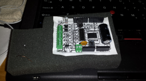
What I have done a couple of times to try to catch problems before it is too late has been to make a 1:1 copy of the board, glue it to some material that allows to stick real parts to it, and then lay out the parts on top, as shown in the following picture:

Nothing earth-shattering but it definitely has been useful and saved me a couple of times.

Upload non-Arduino firmware to Arduino-compatible board

The Atmel AVR family of microcontrollers is our favorite solution for embedded electronic projects. As you know, this family is what the popular Arduino platform uses cialis preis apotheke. However, for our projects we have never used the Arduino integrated development environment (IDE), or Arduino libraries. Instead, we have stuck with AVR libc mainly so we can have more control over our firmware and to try to have firmware with a smaller footprint in terms of both execution and image size.

Because we have not been using the Arduino IDE, we have always uploaded firmware to the AVR microcontroller using an in-system programmer (ISP) (the ISP programmer we use is the inexpensive USBtiny). This has been a requirement because our microcontrollers do not normally have a boot loader that allows them to be flashed via the serial port, unlike the Arduino, which does not expose the SPI through a connector that allows someone to hookup an ISP programmer, and therefore has to be programmed

Recently, however, we bought a Moteino, a very nice Arduino-compatible board, that has a boot loader that is compatible with the Arduino IDE. This required us to come up with a way to upload firmware to this board. We originally thought about soldering an adapter to use the AVR’s Serial Peripheral Interface (SPI), which uses the three signals Serial ClocK (SCK), Master In-Slave Out (MISO) and Master Out-Slave In (MOSI), and then use our USBtiny ISP programmer.

However, it turns out that is a lot easier than that — the AVRDUDE software can actually program Arduino-compatible boards directly, without using the SPI interface. We probably should have guessed this because, as we understand it, the Arduino IDE actually uses AVRDUDE to upload firmware to the target.

A sample AVRDUDE invocation looks like this:

shell$ avrdude -p atmega328p -c arduino -P /dev/ttyUSB2   -y -U flash:w:primus.hex

This is what the command-line arguments do:

  • -p atmega328p: specifies the type of target microcontroller.
  • -c arduino: specifies the programmer type. We understand that stk500v1 should work, and we have seen online references that seem to indicate that is what the Arduino IDE uses, but stk500v1 did not work for us. Instead, our AVRDUDE executable (from Ubuntu 13.10) does have an “arduino” programmer that worked very well.
  • -P /dev/ttyUSB2: this is the device to use to talk to the Arduino-compatible target.
  • -U flash:w:primus.hex: this is the name of the firmware file to upload to the Arduino-compatible target.

When we use our ISP programmer, one argument that we like to use is -y, which increments a 16-bit counter stored in the last two bytes of the AVR EEPROM (this counter has to be initialized with a one-time AVRDUDE invocation that uses the arguments -W <initial counter value>). We found out that the boot loader used by Arduino and Arduino-compatible boards (apparently Optiboot) does not handle AVR EEPROM access, so the use of -y when invoking AVRDUDE to upload flash to the Arduino-compatible board is not possible (and neither is initializing the counter with -Y, nor uploading EEPROM data using -U eeprom:w:data.hex).

But this is a small price to pay for the convenience of uploading our AVR libc firmware without having to use the Arduino IDE.

Mixed Content Blocking in Firefox 23

A website that I use at work all of the sudden started to render in a very broken way. Since we had had similar issues in the past I originally thought that it was a problem on the web application itself. However, after asking a co-worker I learned that the breakage is caused by a new feature that is enabled by default in Firefox 23: mixed content blocking. The feature is explained well at the following URL, but it basically boils down to “Firefox will block HTTP content referenced from a page served over HTTPS”.

https://blog.mozilla.org/tanvi/2013/04/10/mixed-content-blocking-enabled-in-firefox-23/

The feature is a nice security feature. However, I think it has been terribly implemented in my opinion — first, you cannot create persistent exceptions (whitelist); second, you cannot create exceptions for entire domain (you have to create them on a page by page basis) so next time you open a page on the same site that also has mixed content then the mixed content will be blocked too. For the second issue, reading the comments in Mozilla bug 873349 is enlightening.

So, I can appreciate all the work the Mozilla developers have put into this feature but I have no option other than to disable it because it really puts a dent on my productivity. Let’s see if this feature is enhanced in a future Firefox release.

ZoneMinder Memory-Mapped Files

After tweaking the capture image size of some of the IP cameras connected to our ZoneMinder installation we started to get the following error in the ZoneMinder log right after launching a viewer to watch the camera’s video stream:

Got unexpected memory map file size 36865192, expected 9217192

Googling for this error took us to this blog post:

http://jared-oberhaus-tech-notes.blogspot.com/2011/12/im-trying-to-capture-video-from-device.html

Which in turn took us to the ZoneMinder FAQ.

The recommendation is to increase the setting /proc/sys/kernel/shmmaxsize so ZoneMinder has enough memory to memory-map the files it needs during streaming.

However, upon checking our /proc/sys/kernel/shmmaxsize setting we found that it had pretty high setting (the recommended [in the ZoneMinder FAQ] 536870912, for 128 MB of maximum shared memory allocatable at a time), because we had run into the issue before and tried to fix it by following the recommendation in the ZoneMinder FAQ. In addition, the error message indicates that it expects a file with a size that is smaller than it currently has, so increasing the /proc/sys/kernel/shmmaxsize setting would not have fixed the problem.

It turns out that ZoneMinder had created the memory-mapped file for a specific capture image size:

$ ls -l /dev/shm/
 total 90016
 -rw------- 1 www-data www-data 36865192 Apr 9 08:24 zm.mmap.6
 [...]

And when we changed the capture image size to a smaller resolution, the required size of the memory-map filed decreased. However, because ZoneMinder had not been restarted, the memory-mapped file had not been recreated, and it still had the size that ZoneMinder allocated for the original, higher resolution video capture.

Re-starting ZoneMinder caused the memory-mapped file to be recreated, now with the correct size for the new (smaller) capture image size:

$ ls -l /dev/shm/
 total 63016
 -rw------- 1 www-data www-data 9217192 Apr 9 08:47 zm cialis online ohne rezept.mmap.6
 [...]

After this, ZoneMinder did not generate the error anymore.

Update 20130415:

We increased the capture image size of one of the ZoneMinder monitors and received again the “Got unexpected memory map file size …” message, this time indicating that the size of the file is smaller than expected. This makes sense and shows that the issue has nothing to do with the configured value in /proc/sys/kernel/shmmaxsize but with a memory-mapped filed created by ZoneMinder that is not recreated when the size of the image capture is changed. This should be considered a bug in ZoneMinder, in our opinion. We are running ZoneMinder 1.25.0.

Orbit 62035 Redux

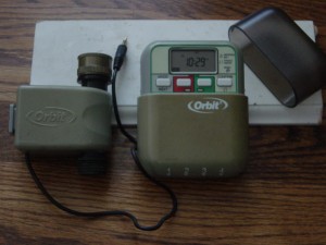
The Orbit 62035 water valve was part of a yard watering system sold by Orbit around 2005 (it has been superseded by a newer generation of valves, and their corresponding timer/controller, although it is probably still possible to find the old valves on Amazon or eBay). This yard watering system, and its valves, were sold in the United States at big retailers like Lowes, The Home Depot, and BJs. We bought two of these systems, which includes a couple of 62035 water valves and their controller (timer) to water our front and back yards, and they have been working wonderfully for about six summers. The following picture shows a 62035 water valve and its controller (click image to enlarge). Note from the picture the 3.5 mm connector and that the controller can control up to four valves.

The controller is pretty good and user-friendly, and the three AA batteries it uses to run last a long time, but for a while we have wanted to be able to control the valves from a computer, or to have more intelligence on the controller itself, like taking into consideration whether it has rained, or that the forecast calls for rain soon, because it is not fun to go outside in the middle of the night and in the middle of a thunderstorm to override the system so it does not waste water the next morning. This sent us into a quest to figure out how to control these valves to then try to build a controller that suits our needs. (Note: Sure, without a doubt there is something that can be bought that will suit our needs, but we also have fun doing this ourselves, which is why we do it.)

What we found was that some people had already, for the most part, figured out the specifications of the valve, and even built drivers to operate them. Here are the relevant links that we found:

There was a lot of information, but some of it seemed contradictory or insufficient. For instance, here is what we were able to gather regarding the valves, their specifications, and how to make them work:

  • There are two latching solenoids, one for opening the valve and another for closing it.
  • The standard 3-pin 3.5mm stereo audio plug used by the valve uses a common contact to supply the voltage required for operation, and separate contacts for the open and close solenoids.
  • The resistance of each solenoid was different. One (the open solenoid) was around 4 ohms, but the other (the close solenoid) had a fairly low resistance of around 1 ohm.
  • The voltage required to operate the valves was not clear — some people thought it was 24 volts, some others claimed it was 17 volts, and then Orbit technical support claimed it was 13 volts.
  • The original Orbit controller works by charging a 2,200 uF capacitor and then discharging it through the solenoids. To charge the capacitor, and because the controller only uses three AA batteries, a voltage booster circuit is used. Our guess would be that the exact value of the capacitor was found after someone opened the original Orbit controller and took a peek at the components inside.
  • In one of the links above someone claims that to close the valve the controller first sends an open pulse followed by the big close pulse.
  • The length of the pulse needed to open or close the solenoids, per someone that apparently watched the operation on an oscilloscope, was around 22 milliseconds, although Orbit technical support provided a different figure.
  • Since the resistance of the close solenoid is so low, there is a 3.9 ohm current-limiting resistor. This was discovered after some people (Ray) opened an original Orbit controller and saw the 3.9 ohm resistors.
  • Orbit support, supposedly, provided the following specifications for these valves: 13V, 22ms pulse and 1 to 1.5 amp current max.

Armed with this information we tried to recreate the circuits that others had designed. We managed to make things to work on a breadboard, with some minor modifications of our own, but when we moved the design to SMT devices on a real PCB, things did not work.

So, to be able to figure out why our SMT design was not working we decided to hook up the original Orbit controller to an oscilloscope and collect some data. This is what we found after we connected an oscilloscope to the original Orbit controller and a 62035 water valve…

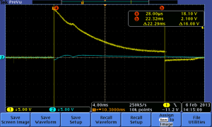
The following oscilloscope screenshot shows the original Orbit controller opening an Orbit 62035 valve (click image to enlarge):

The yellow line is the voltage applied to the solenoid that opens the valve and the blue line is the voltage at the solenoid that closes the valve. The graph shows a capacitor discharging through the solenoid (a resistance with a low value). The initial voltage is 18.1 volts. Not 24 volts as originally thought, and not the 13 volts that Orbit technical support claimed, though both voltages are close. The 0 volts across the close solenoid makes sense. Note also the length of the pulse — 22 milliseconds. The resistance we measured across the solenoid that opens the valve is 4.2 ohms, which means that at the beginning of the discharge there is a peak current of 18.1 volts/4.2 ohms = 4.2 Amps.

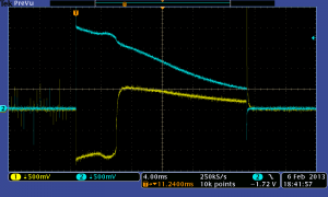
Finally, the following oscilloscope screenshot shows the original Orbit controller closing an Orbit 62035 valve (click image to enlarge):

A few things to note here: First, notice the different vertical scale — 0.5 volts/division. Next, note that we forgot to turn on the cursor so we can easily see the the exact voltage at the trigger point, but it is easy to see that the blue line (voltage across the close solenoid, as in the first screenshot) has a value at trigger point of 4 divisions x 0.5 volts/division = 2 volts. Since the resistance of the close solenoid is different (0.9 ohms), then at the beginning of the discharge the peak current is approximately 2 volts/0.9 ohms = 2.2 Amps. The length of the pulse is also about 20 milliseconds. This opens two possibilities with regards to the value to which the 2,200 uF capacitor is charged: 1. it is charged to a lower voltage than the voltage it is charged to in the case of opening the valve, or 2. it is charged to the same value (~ 18 volts) but there is a resistor in series with the solenoid to limit the current. (2) is what is actually happening based on Ray’s findings, i.e. there is a 3.9 ohm capacitor inside the original Orbit controller, but it would be interesting to experiment with (1) to see if in our design we could somehow (through software, assuming we can control the voltage produced by the voltage booster circuit) eliminate the current limiting resistor.

Another interesting thing to note is the negative voltage across the open solenoid — this seems to be the pulse that one of the people participating in this discussion mentioned, though we are not sure it is the same thing because in the discussion the gentleman says ‘When the Timer/Controller turns a valve OFF, it first operates the “Valve ON” coil, then recharges the capacitor and operates the “Valve OFF” coil’, and we did not see this exact behavior, as the above screenshot shows.

In a future post we will look at how we are planning to control the Orbit 62035 valve based on the information we have learned through the research done by others as well as our own observations.

Capacitor Discharge

I am working on a project that requires activating a latching solenoid cialis auf rezept. I am trying to accomplish this by discharging a capacitor through the solenoid. I have the “supposed” specifications of the voltage, current and pulse time needed for the solenoid to be activated so it helps to understand the behavior of the capacitor discharge. This is Electricity 101, which I studied many moons ago, and which I remember nothing about, unfortunately.

Fortunately, there are plenty of resources out there that explain what happens when a capacitor is discharged through a resistance and calculators that allow you to plug in some basic parameters and then present you with final voltage of the capacitor. Here are some references:

RC circuits: http://en.wikipedia.org/wiki/RC_circuit

Some online calculators that I found:

http://www.learningaboutelectronics.com/Articles/Capacitor-discharge-calculator.php

http://hyperphysics.phy-astr.gsu.edu/hbase/electric/capdis.html

http://planetcalc.com/1979/

BJT Base Resistor Value

It is very common to use <a href="http://en.wikipedia cialis 20mg filmtabletten apotheke.org/wiki/Bipolar_junction_transistor”>bipolar junction transistors (BJT) to drive higher current loads. For example, BJTs is commonly used to drive LEDs, electric motors, relays, etc.

When using a BJT to drive a higher current load a resistor needs to be put between the signal driving the transistor and the transistor’s base. The purpose of this transistor is to limit current going into the base. The resistor’s value is important and should be calculated depending on the circuit’s operating parameters and the load the transistor is driving.

I have never been too serious about calculating base resistor values… until today when a circuit I was working on did not work. Upon closer inspection I realized that I had used in my breadboard prototype a different resistor value than the value of the resistor that I used in the PCB version of the same circuit — in the breadboard test I had used 100 ohms and in the PCB I soldered a 1 kohm resistor. As a consequence, my circuit was not able to drive well the solenoid that I was driving with this transistor. (The mistake, by the way, was caused by incorrect resistor value in the Eagle schematic, which got into my PCB circuit because I was following the schematic and not the breadboard prototype while assembling the PCB. Ggrrr. Note to self: make sure your schematic reflects your working prototype.)

Fortunately, calculating the correct base resistor value is easy, and there are online calculators out there that help with this task. You need to know:

  • Ic — the collector current (the current going through your load)
  • The hFE (gain) of the transistor. This varies depending on the collector current, and its value can be determined from the data sheet
  • The voltage drop across the base to emitter junction. This is called Vbe(sat) in the transistor’s data sheet
  • The voltage used to drive the transistor (at the base). This is typically the voltage supplied by a microcontroller output pin, and is usually very close to the supply voltage to the microcontroller (typical values: 5 V, 3.3V)

Here’s a link to a great online calculator:

http://kaizerpowerelectronics.dk/calculators/transistor-base-resistor-calculator/

The author of this calculator described the formula in the comments of that post as follows:

(Supply voltage – voltage drop) / (Collector current / Hfe)

Finding the parameters needed for this formula (which are very well explained at the top of the above calculator page) is a great way to learn how to read a transistor’s data sheet.