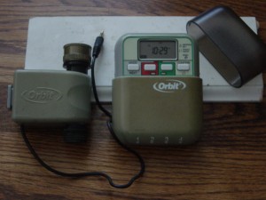
The Orbit 62035 water valve was part of a yard watering system sold by Orbit around 2005 (it has been superseded by a newer generation of valves, and their corresponding timer/controller, although it is probably still possible to find the old valves on Amazon or eBay). This yard watering system, and its valves, were sold in the United States at big retailers like Lowes, The Home Depot, and BJs. We bought two of these systems, which includes a couple of 62035 water valves and their controller (timer) to water our front and back yards, and they have been working wonderfully for about six summers. The following picture shows a 62035 water valve and its controller (click image to enlarge). Note from the picture the 3.5 mm connector and that the controller can control up to four valves.
The controller is pretty good and user-friendly, and the three AA batteries it uses to run last a long time, but for a while we have wanted to be able to control the valves from a computer, or to have more intelligence on the controller itself, like taking into consideration whether it has rained, or that the forecast calls for rain soon, because it is not fun to go outside in the middle of the night and in the middle of a thunderstorm to override the system so it does not waste water the next morning. This sent us into a quest to figure out how to control these valves to then try to build a controller that suits our needs. (Note: Sure, without a doubt there is something that can be bought that will suit our needs, but we also have fun doing this ourselves, which is why we do it.)
What we found was that some people had already, for the most part, figured out the specifications of the valve, and even built drivers to operate them. Here are the relevant links that we found:
- Ray, of Rayshobby/OpenSprinkler fame, wrote a couple of very nice and detailed blog posts that describe how the valve works: How to control Orbit 62035 valve and Update on ‘How to control Orbit 62035 valve’. The comments in Ray’s blog posts also contain some good information.
- Jay Collett created an Arduino shield, based on some of Ray’s work, that can control up to three of these valves: the h2o shield.
- And people participating in this discussion did some testing with the valves and even contacted Orbit technical support to obtain the specifications to operate the valves.
There was a lot of information, but some of it seemed contradictory or insufficient. For instance, here is what we were able to gather regarding the valves, their specifications, and how to make them work:
- There are two latching solenoids, one for opening the valve and another for closing it.
- The standard 3-pin 3.5mm stereo audio plug used by the valve uses a common contact to supply the voltage required for operation, and separate contacts for the open and close solenoids.
- The resistance of each solenoid was different. One (the open solenoid) was around 4 ohms, but the other (the close solenoid) had a fairly low resistance of around 1 ohm.
- The voltage required to operate the valves was not clear — some people thought it was 24 volts, some others claimed it was 17 volts, and then Orbit technical support claimed it was 13 volts.
- The original Orbit controller works by charging a 2,200 uF capacitor and then discharging it through the solenoids. To charge the capacitor, and because the controller only uses three AA batteries, a voltage booster circuit is used. Our guess would be that the exact value of the capacitor was found after someone opened the original Orbit controller and took a peek at the components inside.
- In one of the links above someone claims that to close the valve the controller first sends an open pulse followed by the big close pulse.
- The length of the pulse needed to open or close the solenoids, per someone that apparently watched the operation on an oscilloscope, was around 22 milliseconds, although Orbit technical support provided a different figure.
- Since the resistance of the close solenoid is so low, there is a 3.9 ohm current-limiting resistor. This was discovered after some people (Ray) opened an original Orbit controller and saw the 3.9 ohm resistors.
- Orbit support, supposedly, provided the following specifications for these valves: 13V, 22ms pulse and 1 to 1.5 amp current max.
Armed with this information we tried to recreate the circuits that others had designed. We managed to make things to work on a breadboard, with some minor modifications of our own, but when we moved the design to SMT devices on a real PCB, things did not work.
So, to be able to figure out why our SMT design was not working we decided to hook up the original Orbit controller to an oscilloscope and collect some data. This is what we found after we connected an oscilloscope to the original Orbit controller and a 62035 water valve…
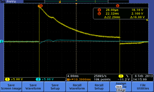
The following oscilloscope screenshot shows the original Orbit controller opening an Orbit 62035 valve (click image to enlarge):
 The yellow line is the voltage applied to the solenoid that opens the valve and the blue line is the voltage at the solenoid that closes the valve. The graph shows a capacitor discharging through the solenoid (a resistance with a low value). The initial voltage is 18.1 volts. Not 24 volts as originally thought, and not the 13 volts that Orbit technical support claimed, though both voltages are close. The 0 volts across the close solenoid makes sense. Note also the length of the pulse — 22 milliseconds. The resistance we measured across the solenoid that opens the valve is 4.2 ohms, which means that at the beginning of the discharge there is a peak current of 18.1 volts/4.2 ohms = 4.2 Amps.
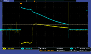
Finally, the following oscilloscope screenshot shows the original Orbit controller closing an Orbit 62035 valve (click image to enlarge):
 A few things to note here: First, notice the different vertical scale — 0.5 volts/division. Next, note that we forgot to turn on the cursor so we can easily see the the exact voltage at the trigger point, but it is easy to see that the blue line (voltage across the close solenoid, as in the first screenshot) has a value at trigger point of 4 divisions x 0.5 volts/division = 2 volts. Since the resistance of the close solenoid is different (0.9 ohms), then at the beginning of the discharge the peak current is approximately 2 volts/0.9 ohms = 2.2 Amps. The length of the pulse is also about 20 milliseconds. This opens two possibilities with regards to the value to which the 2,200 uF capacitor is charged: 1. it is charged to a lower voltage than the voltage it is charged to in the case of opening the valve, or 2. it is charged to the same value (~ 18 volts) but there is a resistor in series with the solenoid to limit the current. (2) is what is actually happening based on Ray’s findings, i.e. there is a 3.9 ohm capacitor inside the original Orbit controller, but it would be interesting to experiment with (1) to see if in our design we could somehow (through software, assuming we can control the voltage produced by the voltage booster circuit) eliminate the current limiting resistor.
Another interesting thing to note is the negative voltage across the open solenoid — this seems to be the pulse that one of the people participating in this discussion mentioned, though we are not sure it is the same thing because in the discussion the gentleman says ‘When the Timer/Controller turns a valve OFF, it first operates the “Valve ON” coil, then recharges the capacitor and operates the “Valve OFF” coil’, and we did not see this exact behavior, as the above screenshot shows.
In a future post we will look at how we are planning to control the Orbit 62035 valve based on the information we have learned through the research done by others as well as our own observations.


Can you make me one? After many years of good use mine have given out and I am in need of one and am unsure if the valves work with any of the newer timers.
Hi Miguel,
These old valves will not work with the new timers — the new timers generate positive/negative pules to open/close the valves, so the connection to the valves is different (because only two wires are required). The old valves require two positive pulses to operate them, so three wires are required: pulse 1, pulse 2, and ground, so the connector has three wires.
I’ll be publishing soon my design to operate these valves. My designed is based on the work of some of the people mentioned in the blog post.
Cheers,
Eloy Paris.-
Thanks for the interesting info. Did you have a chance to try further experiments with this valve?
I’m particularly interested in the story with the Close operation – the dual-pulse you are seeing on the oscilloscope.
I have quite a few of these old Orbit valves accumulated but without controllers (they tend to die in few years), and I’m considering doing a converter to connect these valves to a regular 24VAC timer. Your information is very helpful.
Hi Tony,
I haven’t done further experimentation because I think there’s nothing else to understand about how these valves operate. I have a design to control the valves and it seems to be working fine. I am still working on finishing microcontroller firmware but that’s a separate story. Once I have something usable (meaning: something that I use in my house) I’ll publish my design under an open source license.
I think the dual pulse that I saw is just an artifact — I don’t think the original timer was generating it because, if I remember correctly, I saw the dual pulses when testing with my own controller, which does not generate dual purposes on purpose.
Cheers,
Eloy Paris.-
Hey Tony,
Where you able to build a controller for your Orbit 62035 valves? I’ve got timers, but all of my valves are dying and I’d be interested in obtaining some of your accumulation if you’re not able to use them.
Thanks.
I have a couple of the 62032 timers and 1 (out of 8 valves) that still works.
did you ever figure out how to use the newer 2 wire orbit valves or standard 2 wire sprinkler valves?
and if anyone has some working timers and valves for sale let me know. i could use more valves, and a spare timer would be nice.
Couple of questions come to mind:
– would the valves work if the polarity were reversed?
– would the valves work if the 24 volts were ac?
Hi Tim,
I am not an expert but I believe these are DC solenoids and if so they cannot be driven by AC current.
Regarding the polarity, I am not sure but I don’t think that would work because there are two solenoids in these valves — a negative voltage (and thus a negative current) would help the other solenoid but you would still need a positive voltage to drive the other solenoid. Based on the behavior that I observed when using the original timer, I didn’t try applying a negative voltage to test, though.
Cheers,
Eloy Paris.-
“… the following oscilloscope screenshot shows the original Orbit controller closing an Orbit 62035 valve (click image to enlarge):”
The photo is not linked to the enlargement.
Thank you; fixed.